Products
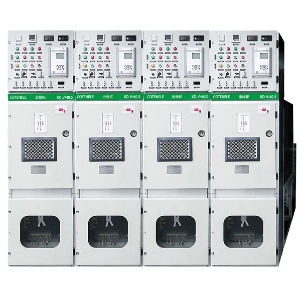
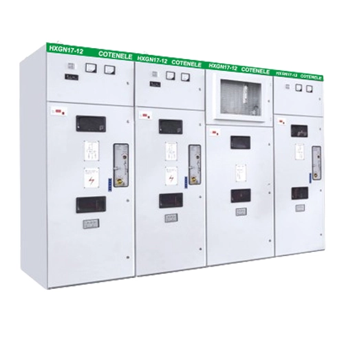
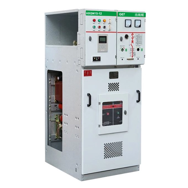
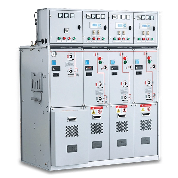
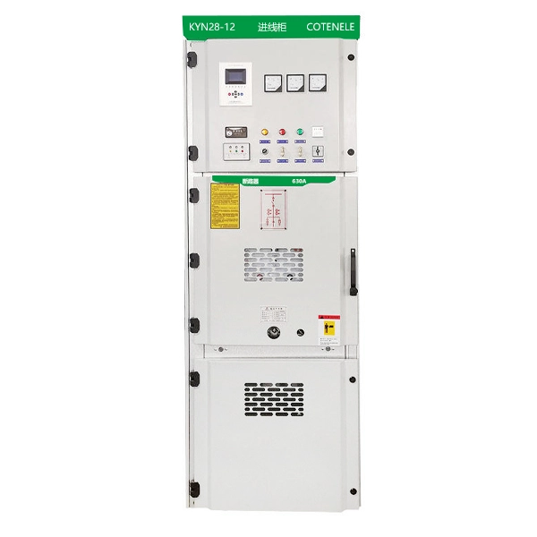
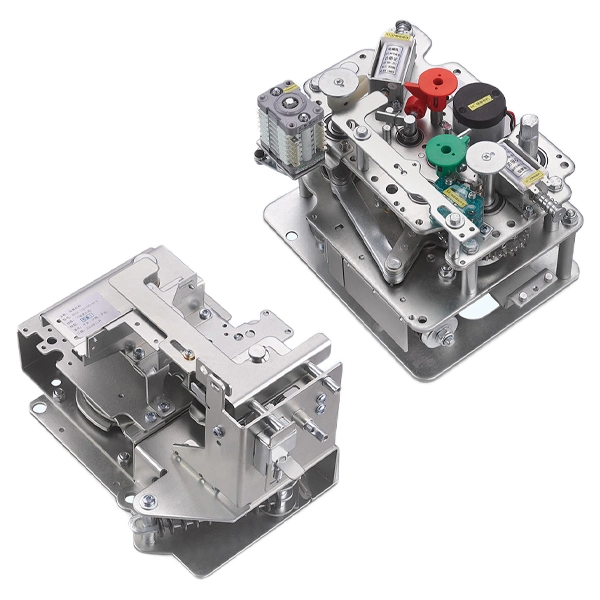
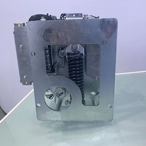
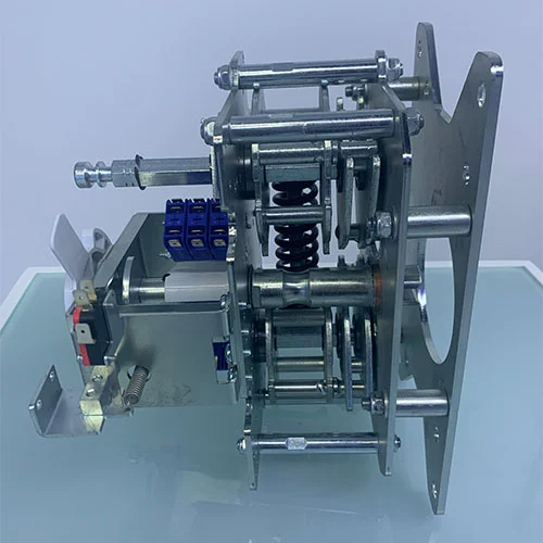
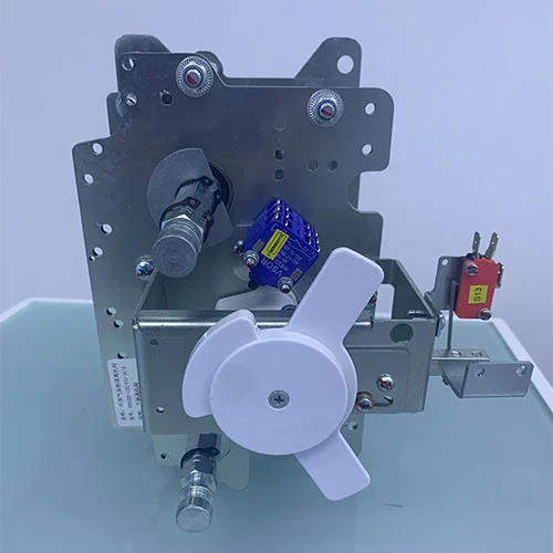
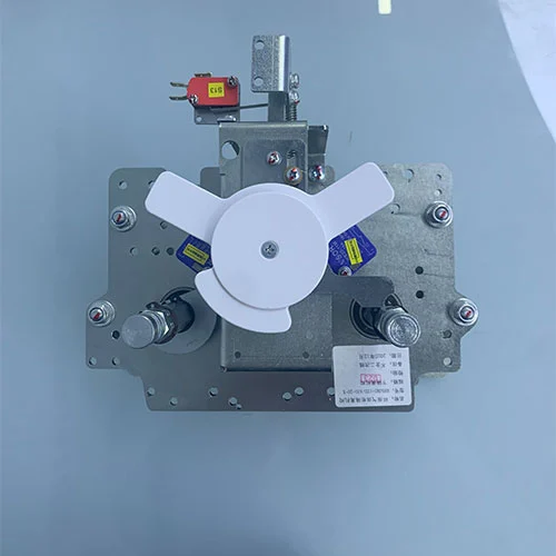
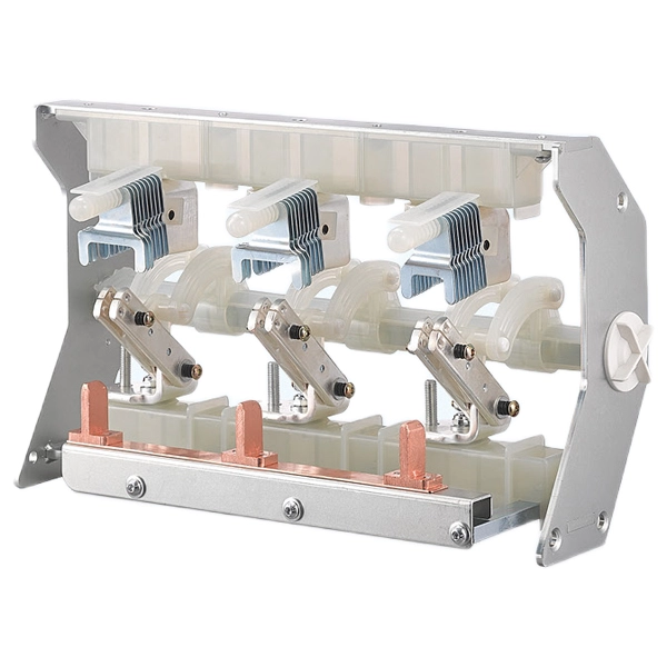
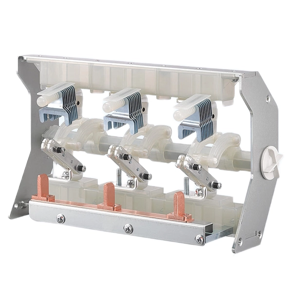
11KV MV Switchgear Circuit Breaker Isolation Mechanism
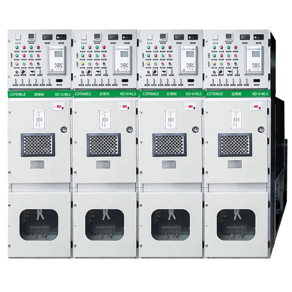
Cotenele, a professional manufacturer in China, produces the 11kV MV Switchgear Circuit Breaker Isolation Mechanism, a core component of ring main units. These mechanisms are designed to provide safe, high-speed protection and reliable electrical isolation. We specialize in providing medium-voltage switchgear and ring main unit solutions for power, railway, petrochemical, municipal, and renewable energy projects.
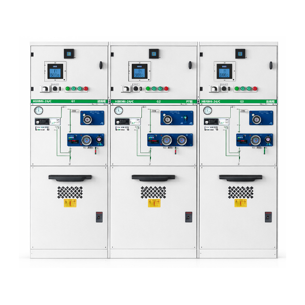
The 11KV MV Switchgear Circuit Breaker Isolation Mechanisms are essential for the operational safety and reliability of medium-voltage switchgear, particularly Ring Main Units (RMUs). RMUs are compact, metal-enclosed switchgear devices widely used in power distribution networks to provide reliable switching, protection, and isolation.
Inside these switchgears, two mechanisms operate together but serve different purposes:
Circuit Breaker Operating Mechanism - actively interrupts load and fault currents.
Isolation Mechanism - passively ensures personnel safety by providing visible and reliable electrical isolation.
The interlocked operation between these mechanisms guarantees both equipment protection and human safety, making them indispensable in industrial and utility applications.
Product Model
| KD | VM | 12 | 630 | 20 | X |
|
Company code |
Vacuum circuit breaker Operating mechanism |
Rated voltage |
Rated current |
Rated Short-time withstand current | Lower isolator |
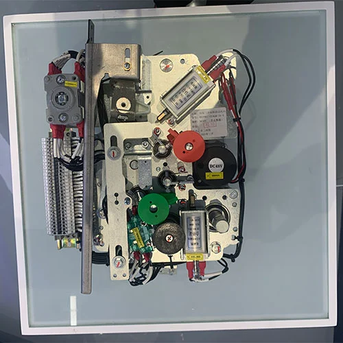
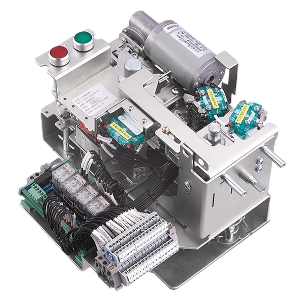
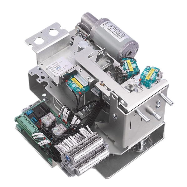
Components of the operating mechanism
The 11KV MV Switchgear Circuit Breaker Isolation Mechanism is a critical component used in medium-voltage (MV) ring main units (RMUs) and eco-friendly switchgear systems. It integrates both circuit breaker operating mechanisms and isolating mechanisms, ensuring reliable power control, fault protection, and safe maintenance operations.
What Is A Circuit Breaker Operating Mechanism?
The Circuit Breaker Operating Mechanism is usually used for controlling the main circuit breaker in the medium-voltage RMUs or eco-friendly switchgear. The operation mechanism primary function is to facilitate the opening and closing of the breaker contacts (often vacuum interrupters) to handle load currents and, critically, to interrupt fault currents (short circuits).
Functionality
It must be capable of making, carrying, and breaking currents under normal and abnormal conditions. When a fault occurs, this vacuum circuit breaker operation mechanism must operate to clear the fault and protect downstream equipment in milliseconds.
Energy Storage
The difference with a simple manual switch is the vacuum circuit breaker operation menchanis relies on stored energy to achieve the high-speed motion required for arc interruption. This mechanism energy storage is usually achieved from spring-charged mechanisms (which can be charged manually or by a small motor) or magnetic actuators. The energy is stored slowly over several seconds but released instantaneously when the mechanism get command.
Components
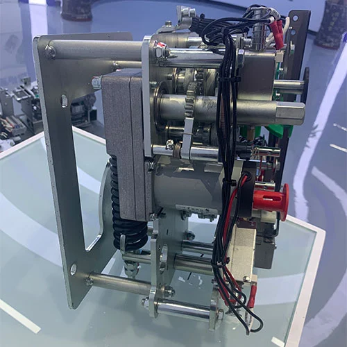
A typical mechanism includes closing springs, opening springs, a charging motor, trip and close solenoids, and a complex linkage of cams and shafts. It is designed for thousands of operations over its lifetime.
What Is A Isolating Mechanism?
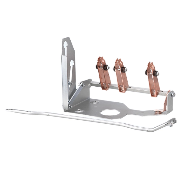
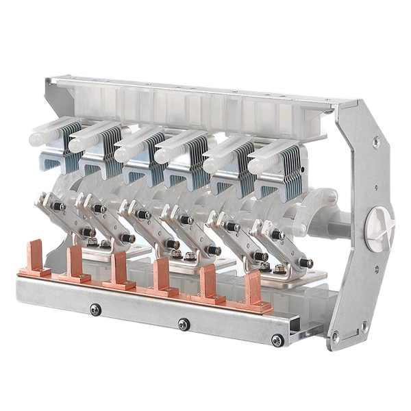
The Isolating Mechanism governs the operation of the disconnector (isolator) and the integrated earthing switch. Unlike a circuit breaker, its purpose is not to interrupt current but to provide a safe working condition for maintenance personnel.
Functionality
Its primary job is to create a visible and reliable galvanic isolation between a de-energized circuit and the live power source. The switch disconnector operation mechanism in the medium-voltage RMUs or eco-friendly switchgears geerally also integrates earthing switch, which connects the isolated circuit to the ground. This step discharges any trapped capacitive charge and protects against accidental back-feed from other sources.
Operation
These isolation switch operation mechanisms are manually and electrically operated by an external handle inserted into the switchgear front panel. The handle turns operating shafts connected to a system of levers and cams, which move the isolator contacts.
Key Safety Feature
The isolating mechanism operates at a relatively slow, manual speed or directly electric and has no arc-quenching capability. Therefore, it is strictly prohibited from being opened when the device is charged. It relies on the insulating properties of the surrounding medium (air or SF6 gas) to maintain isolation once open.
Main Differences Between the Two Mechanisms
| Circuit Breaker Mechanism | Isolating Mechanism | |
| Primary Goal | Protection &Interruption | Isolation &Grounding |
| Current Handling | Makes and breaks load and fault current. | Makes and breaks negligible current (only after breaker opens). |
| Speed | High-speed operation (milliseconds)to quench arcs. | Slow,manual operation;no arc quenching capabiity. |
| Energy Source | Stored energy(Springs,Magnets). | Manual human force. |
| Contact Visibility | Contacts are sealed in a vacuum bottle; position is indicated externally. | Designed to provide a verifiable physical gap or relies on clear indicators. |
| Interlocking Role | Sends status signals to allow or block isoator operation. | Mechanically locked to prevent operation unless breaker is confirmedopen. |
Working Principle of these two operation mechanisms combination: Interlocking for Safety
The safe operation of a ring main unit (RMU) relies on a strict mechanical interlock between the circuit breaker mechanism and the isolation mechanism. Our 11kV MV Switchgear Circuit Breaker Isolation Mechanism must be performed strictly according to a predetermined sequence and in accordance with fundamental electrical safety rules.
The following feeder power outage maintenance workflow demonstrates their synergy:
Open the Breaker
when the operator sends a trip command, the circuit breaker operation mechanism will release the stored spring energy, and will open the circuit breaker contacts, then the load current will be interrupted safely. The circuit is de-energized but not yet safe at this moment, because a solid electrical connection to the supply still exists.
Open the Isolator
Now the interlocking system releases the mechanical lock on the Isolating Mechanism after sensing the circuit breaker is open . The operator inserts the handle and turns the shaft to open the isolator. This action will create a physical air gap between the live busbar and the downstream circuit, this will establish visible isolation.
Close the Earth Switch
The operator then uses the same (or a separate) interface to engage the earthing switch via its dedicated mechanism. This connects the downstream part of the circuit directly to ground potential, ensuring any residual charge is safely discharged.
Final Safe State
The breaker is open, the isolator is open, and the earth switch is closed. The mechanical interlocks ensure that the cabinet door cannot be opened unless the earthing switch is confirmed closed. On the contrary, this interconnected system will physically prevent the circuit breaker from closing unless the isolation switch is fully closed and the grounding switch is in the open state. This forms an unbreakable security chain.
The circuit breaker mechanism acts as an active protector, managing the energy of the power grid. The isolation mechanism acts as a passive safety lock, ensuring the safety of management personnel. They will form a comprehensive system together, in which high-speed protection is balanced with absolute, mechanically enforced safety.
Operation Instructions
Charging Operation: Before any closing action can take place, the mechanism must first be charged to store the necessary energy. For manual charging, insert the dedicated handle onto the operating shaft located on the lower right side of the mechanism and rotate it clockwise. Continue turning until a distinct "click" is heard, which signals that charging is complete; at this moment, the charging indicator shaft will have activated the micro-switch to its fully closed position. For electric charging, simply apply power to the mechanism, and the motor will automatically run to store energy. Once the battery is fully charged, the motor circuit will be cut off, while the mechanical device will remain in standby mode, and the stored energy will be retained until the shutdown command is received. Before relying on electric charging operation, it is necessary to ensure that all auxiliary lines are connected correctly.
Closing Operation: With the mechanism successfully charged, the breaker can be closed to complete the main circuit. To close manually, press the green button firmly; this action instantaneously releases the stored closing energy, allowing the mechanism to drive the circuit breaker contacts together. For electrical operation, it is necessary to turn on the power to activate and close the electromagnetic coil, which will immediately trigger the action and release the mechanical lock.The stored energy is then discharged, closing the main contacts. It is important to note that during this process, the opening springs are simultaneously tensioned in preparation for a future trip. Although the mechanism may immediately start recharging, the internal interlock logic will prevent any subsequent closing instructions from being executed until the circuit breaker is opened again.
Opening Operation: To interrupt the circuit and disconnect the circuit breaker, the opening mechanism must be triggered.For manual tripping, press the red button firmly, which releases the latches holding the opening springs. The energy stored in these springs will be instantly released, driving the device to separate the main contacts. For electrical tripping operations, the shunt tripping electromagnet can be powered on and activated through protective relays or remote commands; The electromagnet will immediately activate, releasing the spring lock and forcing the contacts to separate. This operation can safely cut off the current and restore the circuit breaker to the open position, preparing for the next charging and closing cycle.
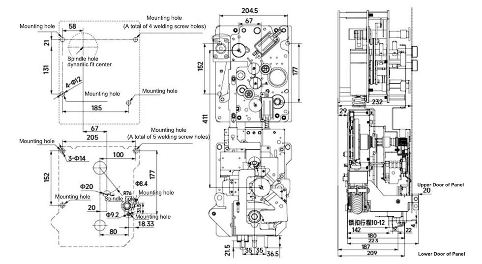
Appearance and Dimensions
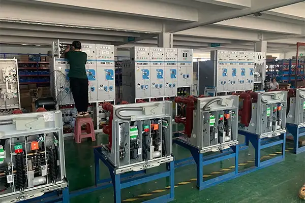
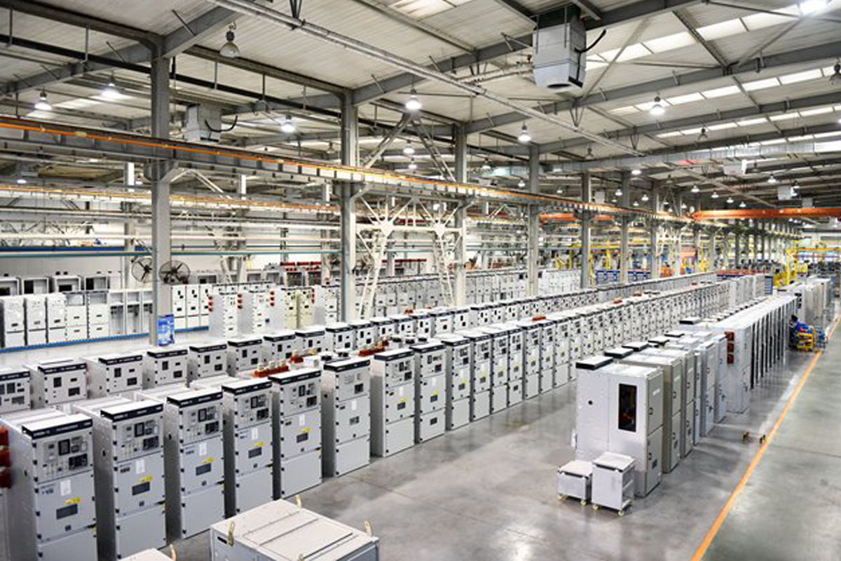
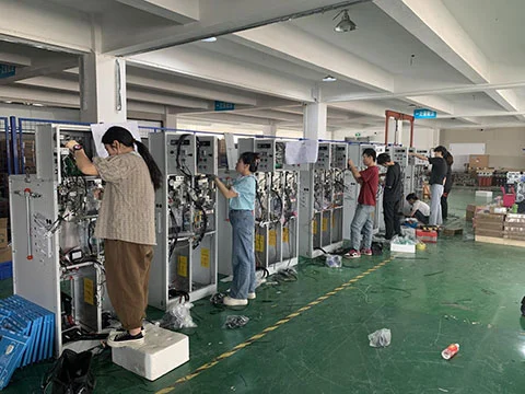
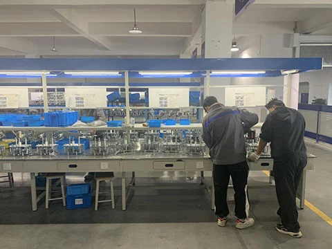
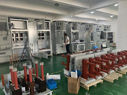
Our Factory
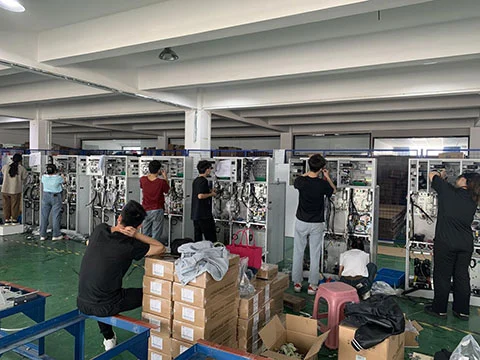
Products Show
Send Inquiry
Contact Info
-
Address
Building 2, Changhong Industrial Park, No. 501 Liule Road, Liushi Town, Yueqing City, Wenzhou City, Zhejiang Province, China
-
Tel
-
Email
Mobile/WhatsApp:
Related Products
News Recommendations