
News
What Factors Should Engineers Consider When Selecting Medium Voltage Switchgear?
Introduction: A Decision That Echoes for Decades
Selecting medium voltage switchgear is not a transaction. It is a design decision that will shape a facility's electrical safety, operational flexibility, and maintenance budget for twenty to thirty years. Unlike components that can be swapped out during a routine shutdown, switchgear is structural. Once the busbars are installed, the panels are bolted together, and the cables are terminated, changing the equipment configuration becomes a major capital project.
Yet in the pressure of project deadlines, switchgear selection is often reduced to checking a few parameters on a datasheet and comparing prices. This approach misses the factors that actually determine whether the equipment will perform reliably over its service life, remain compliant with evolving regulations, and adapt to changes in the facility's electrical load profile.
This article identifies the factors that experienced engineers consider when selecting medium voltage switchgear—not just the parameters that appear on a nameplate, but the operational, regulatory, and lifecycle considerations that separate a specification that performs from one that creates problems later.
Factor One: Understanding the Application Before Looking at Equipment
The single most common error in switchgear selection is starting with the equipment catalog before fully understanding the application. The correct sequence begins with a clear definition of what the switchgear must do, not just what it must withstand.
An incoming feeder serving a utility transformer has fundamentally different requirements from an outgoing feeder supplying a large motor. The incoming breaker sees relatively few operations but must coordinate with upstream utility protection. The motor feeder sees frequent starts and stops, may require surge protection, and needs a protection scheme that distinguishes between starting inrush and a genuine fault. Specifying the same breaker for both applications without considering these differences leads to nuisance tripping, excessive maintenance, or inadequate protection.
The operating environment also shapes the specification. Indoor installations in clean, climate-controlled electrical rooms permit equipment designs that would fail quickly in outdoor or harsh industrial environments. A switchgear panel rated for a data center electrical room, with its stable temperature and low humidity, is not the same specification as a panel destined for an offshore platform or a desert solar installation. Condensation, salt spray, airborne dust, and extreme temperature swings each impose design requirements that the specification must address.
Engineering hours spent defining the application before the equipment search begins are never wasted. They are the cheapest insurance against a specification error that compounds over decades of operation.
Factor Two: The Core Switching Technology
The choice of circuit breaker technology determines the switchgear's fundamental character: its maintenance profile, its safety characteristics, and its environmental footprint.
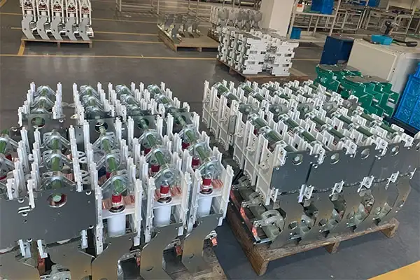
Vacuum circuit breakers have become the standard for medium voltage applications from 3.3 kV to 40.5 kV. The reasons are well-documented: the vacuum interrupter extinguishes the arc inside a sealed ceramic bottle that requires no maintenance for its entire service life. There is no oil to test, filter, or replace. There is no gas to leak or monitor. The interrupter is indifferent to the source of the fault current it must interrupt, making it well-suited to grids with high renewable energy penetration where fault characteristics may differ from traditional synchronous generation.
SF₆ circuit breakers, once common in medium voltage applications, are now in retreat. The EU F-gas Regulation has prohibited new SF₆ switchgear up to 24 kV from the European market, and similar restrictions are advancing globally. Even where regulations have not yet taken effect, the direction of policy is clear. Specifying SF₆ equipment today creates a future compliance liability and rising operational costs for gas handling, leak detection, and eventual end-of-life recovery.
The practical question for engineers is not whether to choose vacuum interruption—that debate is largely settled. The question is which specific vacuum circuit breaker design and which manufacturer best meets the project's requirements for mechanical endurance, interrupting capacity, and compatibility with the chosen panel configuration.
Factor Three: Rated Parameters and Their Margins
The rated parameters on a switchgear datasheet—voltage, current, short-circuit breaking capacity—are the minimum entry criteria. What separates a robust specification from a marginal one is the margin between the rated value and the actual operating condition.
Rated voltage must exceed the nominal system voltage with allowance for temporary overvoltages during faults or switching events. A 12 kV system may see transient voltages considerably higher than the nominal value. The switchgear's power-frequency withstand voltage and lightning impulse withstand voltage must accommodate these conditions with margin, not just meet the minimum standard.
Rated continuous current deserves particular attention because it is frequently underspecified. The nameplate rating assumes specific ambient conditions—typically 40°C maximum, with an altitude ceiling of 1000 meters. If the installation is in a region where ambient temperatures regularly exceed 40°C, or at an altitude above 1000 meters where thinner air reduces cooling efficiency, the rated current must be derated. A 1250 A breaker installed at 3000 meters may only be capable of carrying 1050 A continuously. If the load is close to the nameplate rating under standard conditions, it will exceed the derated capacity under actual site conditions.
Short-circuit breaking capacity must be compared against the calculated fault level at the point of installation, not against a standard value pulled from a previous project specification. Urban networks with high load density and multiple transformer connections can produce fault levels that surprise engineers accustomed to less densely interconnected systems. A short-circuit study performed for the specific installation, using current system data and projected future generation, is the only reliable basis for specifying this parameter.
Short-time withstand current—the current the breaker must carry in the closed position for a specified duration while a downstream device clears the fault—is equally important for selective coordination. If a feeder breaker is intended to ride through a fault while an upstream breaker trips, its short-time rating must match that requirement. Overlooking this parameter leads to cascading trips and unnecessary outage extension.
Factor Four: Insulation Medium and Environmental Compliance
The medium that provides dielectric insulation between phases and to ground has become a decision with regulatory, environmental, and operational dimensions that extend well beyond electrical performance.
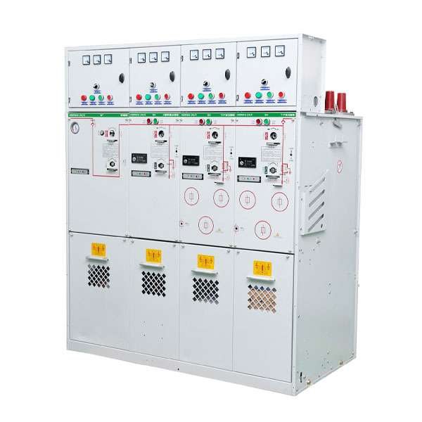
Air-insulated switchgear remains the simplest and most widely used technology. It uses ambient air as the insulating medium, with physical clearance between phases providing the dielectric strength. Air insulation is well-understood, requires no special handling, and imposes no environmental liability. The trade-off is size: air-insulated panels are larger than gas-insulated equivalents, which matters in applications where space is constrained or expensive.
SF₆ gas-insulated switchgear, which dominated compact medium voltage installations for decades, is now being phased out by regulation. For new projects in European and other regulated markets, SF₆ is not an option for equipment up to 24 kV. Even for higher voltage classes, the direction of policy is clear. Engineers should specify SF₆-free alternatives unless a specific exemption applies and has been verified.
Dry air and nitrogen insulation have emerged as the primary replacements for SF₆ in gas-insulated equipment. Both gases have zero global warming potential. Both are non-toxic and require no special end-of-life handling. The sealed stainless steel tank used in modern dry air or N₂ insulated switchgear is filled at the factory and sealed for life—no pressure monitoring, no refilling, and no gas-related maintenance for the equipment's entire service life.
Solid insulation, using epoxy resin encapsulation of live parts, offers another SF₆-free pathway. It eliminates gas entirely, which makes it attractive for harsh environments and space-constrained installations. The trade-off is that solid-insulated designs are less flexible when reconfiguration is needed.
For engineers specifying switchgear today, the insulation medium decision is increasingly straightforward: choose an SF₆-free technology, verify that the manufacturer has completed type testing to applicable IEC standards, and confirm that the documentation package supports environmental compliance claims.
Factor Five: Fixed Versus Withdrawable Configuration
The choice between fixed and withdrawable construction is fundamentally a decision about how maintenance will be performed over the equipment's service life.
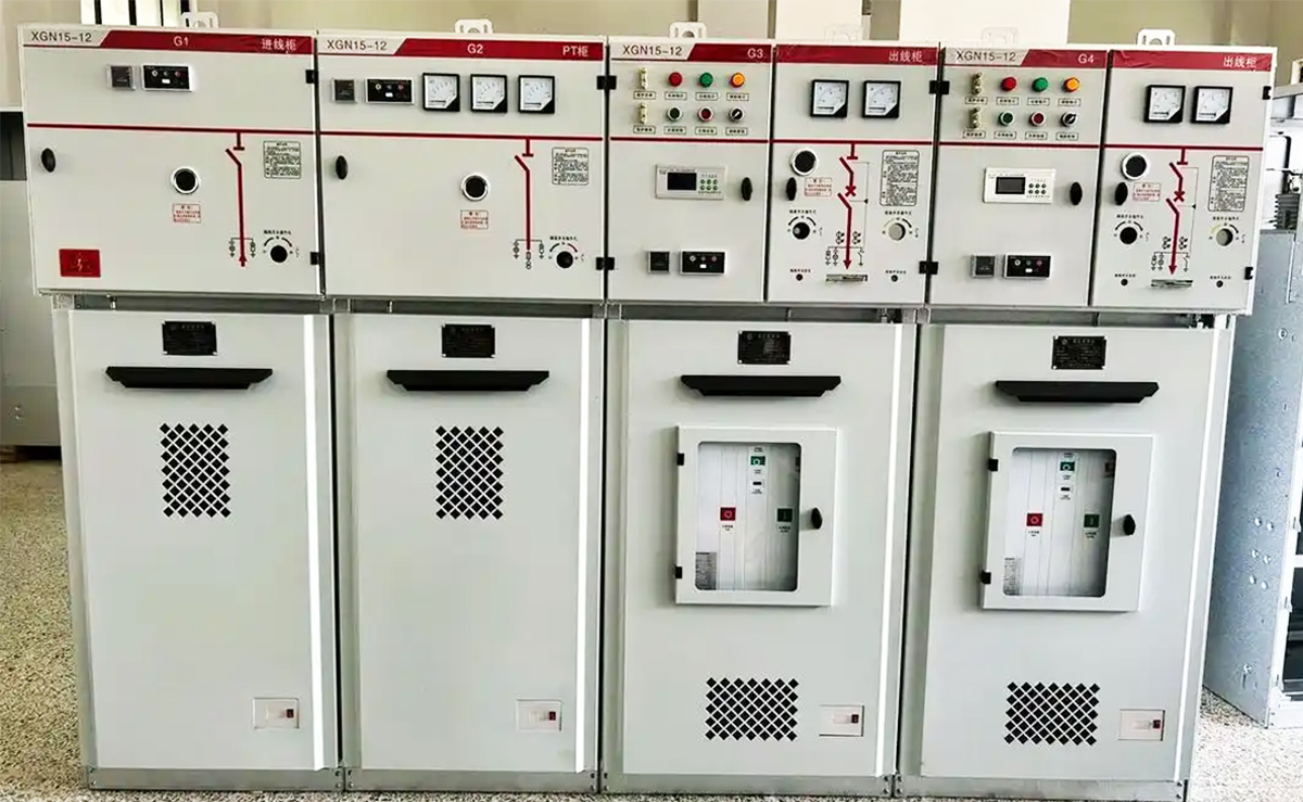
Fixed switchgear has circuit breakers and switches permanently mounted in the panel. It is simpler in design, lower in initial cost, and requires fewer mechanical components that could fail. The trade-off is that any maintenance on the switching device requires de-energizing the entire bus section. For facilities where outage windows are available and the cost of downtime is manageable, fixed switchgear can be an appropriate choice.
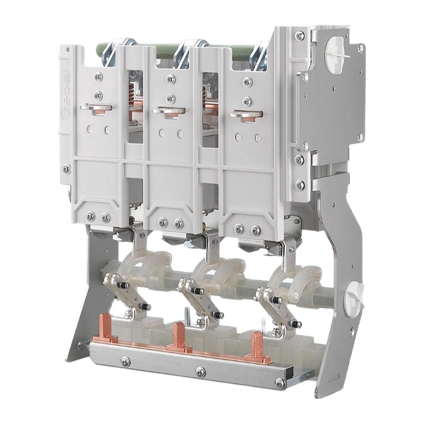
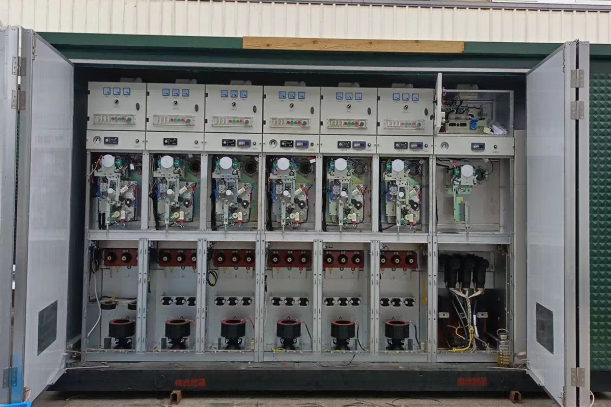
Withdrawable switchgear mounts the circuit breaker on a truck that can be racked in and out of the panel. When the breaker is in the connected position, it is fully engaged with the primary and secondary circuits. It can be racked out to a test position where the primary circuit is disconnected but secondary circuits remain connected for testing. It can be fully withdrawn to an isolated position for maintenance or replacement. This configuration allows a breaker to be serviced or replaced without de-energizing the busbar, which is critical in facilities where downtime is extremely expensive or where continuous operation is contractually required.
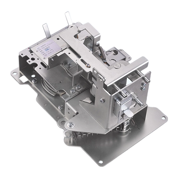
The withdrawable configuration imposes additional mechanical requirements. The truck must align precisely with the panel. The primary contacts must engage with consistent contact pressure. The mechanical interlocks that prevent misoperation—racking a closed breaker, closing a breaker in an intermediate position—must function reliably over thousands of operations. These are not features that can be verified from a photograph. They require manufacturing precision that comes from experience and quality control discipline.
For critical applications—data centers, continuous-process industrial plants, hospitals—the withdrawable configuration is usually the correct choice despite its higher initial cost. The ability to maintain or replace a breaker without shutting down the bus is a capability that pays for itself the first time it is used.
Factor Six: Protection, Control, and Communication
A circuit breaker without a protection relay is a switch with no intelligence. The selection of protection, control, and communication systems is as important as the selection of the breaker itself.
Modern numerical protection relays offer capabilities that go far beyond basic overcurrent and earth fault protection. They can discriminate between different fault types, store waveform records for post-event analysis, and communicate with upstream SCADA or energy management systems via IEC 61850, Modbus, or other protocols. For an engineer, specifying a relay with the right protection functions for the application—motor protection, transformer differential, feeder management—is a task that requires understanding both the equipment being protected and the relay's configuration options.
The communication interface is increasingly important. A switchgear panel that can report its own status—breaker position, protection events, equipment condition—reduces the need for physical inspection and enables condition-based maintenance. For a utility with hundreds of substations, or a data center operator managing multiple facilities, this capability directly reduces operational cost.
Auxiliary power for protection and control must be considered carefully. Most modern protection relays and trip coils operate on DC power, typically 110 V or 220 V DC, supplied by a station battery system. The battery, charger, and DC distribution panel are integral to the protection scheme. If the station battery fails, the protection relays lose power and the breakers will not trip on a fault. This is not a hypothetical scenario—it has caused real-world incidents where a fault went uncleared because the protection system was dark.
Factor Seven: Busbar Configuration and System Architecture
The arrangement of busbars within the switchgear assembly determines how power flows through the system and how the system behaves when a component fails.
A single busbar is the simplest and lowest-cost configuration. All incoming and outgoing feeders connect to one common bus. If the bus fails or the single incoming transformer is lost, all connected loads lose power. This configuration is suitable where the consequence of a total outage is tolerable.
A sectionalized busbar adds a bus coupler circuit breaker that can split the bus into two independently powered sections. If one transformer or bus section fails, the coupler closes and the healthy transformer supplies both sections. The loads experience a brief interruption during transfer. This is the most common configuration for medium-complexity installations.
A main-tie-main configuration uses two independent bus sections, each with its own main incoming breaker and transformer, with a normally-open tie breaker between them. Automatic transfer schemes can close the tie breaker within seconds of detecting a loss of supply on either side. This configuration provides higher reliability and is standard for critical facilities.
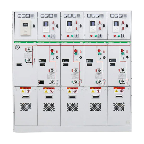
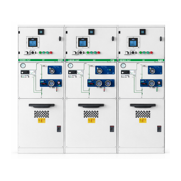
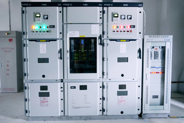
A ring main unit configuration connects multiple switchgear panels in a closed loop. Power can flow in either direction around the ring. A cable fault between any two panels can be isolated without interrupting supply to any load. This configuration is the standard for urban distribution networks, university campuses, and wind farm collector systems.
The busbar configuration should be selected based on the facility's reliability requirements, not on a default specification carried forward from a previous project. A reliability analysis that considers the cost of downtime, the probability of component failure, and the time required for repair or replacement provides a rational basis for this decision.
Factor Eight: Standards Compliance and Documentation
Type testing to IEC 62271-200 is the minimum requirement for medium voltage switchgear in international markets. But "type-tested" is a term that gets used loosely. The question engineers should ask is not "has this equipment been type-tested" but "can you provide the complete type-test reports from an independent IEC-accredited laboratory—right now?"
A manufacturer that has completed the full test program will share the certificates without hesitation. A manufacturer that uses phrases like "design verified to IEC standards" or "test reports in progress" is communicating that the paperwork does not exist yet. For projects where the equipment will be reviewed by a consultant or a utility engineer, this distinction matters.
Beyond type testing, the documentation package that accompanies the switchgear is part of the product. Routine test reports from the factory for every panel. A declaration of conformity to applicable regulations. A reference list of installations. For European projects, documentation demonstrating compliance with the EU F-gas Regulation if the equipment is SF₆-free. These documents should be available at tender stage, not after the order is placed. A supplier who cannot provide them at the inquiry stage is unlikely to produce them promptly later.
Factor Nine: Manufacturer Capability and Long-Term Support
Switchgear is not a commodity. The manufacturer's engineering capability, quality control discipline, and long-term commitment to the product line directly affect the equipment's performance and the availability of support over its service life.
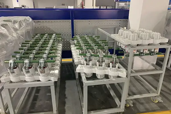
Manufacturing quality shows up in details that are not visible in a brochure. The consistency of epoxy resin pole castings. The alignment of withdrawable truck mechanisms. The routing and labeling of control wiring in the low-voltage compartment. These are process-dependent outcomes that reflect the manufacturer's production culture, not just their design capability.
Long-term support matters because switchgear stays in service for decades. Spare parts availability, technical support for protection relay configuration, and the ability to supply additional panels that match the existing installation—these are considerations that become important years after the initial order.
A factory visit tells an engineer more about a manufacturer than any set of documents. Walking the production line reveals the tooling, the testing procedures, the quality control checkpoints, and the general level of organization that will determine the consistency of the equipment delivered. If a factory visit is not possible, asking for detailed photographs of the production line, testing facilities, and recent completed orders provides useful insight.
Conclusion
Selecting medium voltage switchgear requires looking beyond the datasheet to the application context, the operational environment, the regulatory framework, and the manufacturer's capability. The parameters on the nameplate are the starting point, not the finish line.
An engineer who has defined the application requirements, verified the fault levels, selected an insulation technology that meets current and foreseeable regulations, chosen the configuration that supports the facility's maintenance philosophy, specified the protection and communication systems appropriate for the installation, and qualified a manufacturer with proven production capability and documentation readiness—that engineer has done the work that prevents problems from appearing five, ten, or twenty years after commissioning.
COTENELE supports engineers throughout the specification process with type-tested switchgear, complete documentation packages, and direct access to our engineering team. Our vacuum circuit breakers and SF₆-free ring main units serve utilities, data centers, renewable energy developers, and industrial buyers across multiple continents. Whether you need a standard configuration or a custom solution, we provide the technical data and application support to help you specify with confidence.
Need Technical Data for Your Switchgear Specification?
COTENELE supplies 12kV to 40.5kV vacuum circuit breakers, SF₆-free ring main units, and complete metal-clad switchgear designed to meet the specifications discussed in this article. Type-test reports, routine test documentation, and engineering support available at the specification stage.
About COTENELE
COTENELE is a specialized manufacturer of medium voltage switchgear, including SF₆-free eco-friendly gas insulated switchgear, vacuum circuit breakers, ring main units, and metal-clad panels for 12 kV to 40.5 kV applications. Our products serve utilities, data center operators, renewable energy developers, and industrial buyers across Europe, Asia, and the Middle East. Every product is type-tested to applicable IEC standards, with complete documentation provided for tender submission and project delivery.
Related News
Leave me a message