
News
How Medium Voltage Switchgear Works in Power Distribution Systems
The Backbone Between Generation and Consumption
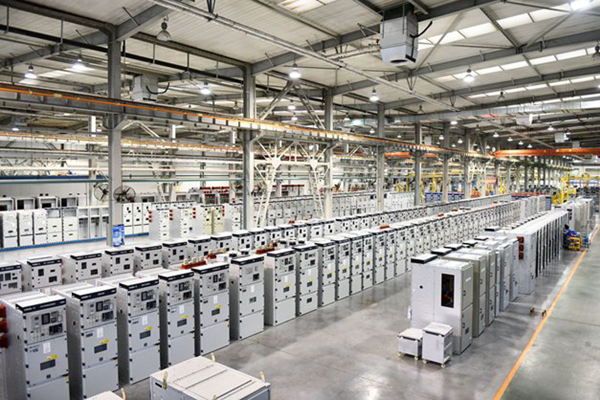
Walk through any modern city and you will pass dozens of installations that depend on medium voltage switchgear without ever seeing one. They sit inside unmarked buildings, behind substation fences, in the basements of commercial towers, and at the edge of industrial parks. They are the electrical nodes where power transitions from transmission-level voltage to the voltage that factories, data centers, hospitals, and apartment blocks actually use.
Medium voltage switchgear occupies a specific place in the power distribution chain. It sits between the high voltage transmission network—110 kV, 220 kV, or 400 kV lines that carry power across long distances—and the low voltage distribution network at 400 V or 230 V that connects to end-user equipment. The medium voltage range, typically defined as voltages above 1 kV and up to 40.5 kV or 52 kV depending on the standard being applied, is where bulk power is subdivided and routed to different loads across a facility or a geographic area.
This article explains how medium voltage switchgear works at the system level, what functions it performs, and why the choices made in switchgear specification affect the safety, reliability, and operating cost of the entire distribution network downstream.
Where Medium Voltage Switchgear Sits in the System
To understand what medium voltage switchgear does, it helps to trace the path of power from the grid to a load.
A typical industrial or commercial facility receives power from the local utility at medium voltage—10 kV, 11 kV, 20 kV, or 33 kV are common depending on the country. This power arrives through underground cables or overhead lines and enters the facility's main switchboard, which is a medium voltage switchgear assembly. From there, it flows through circuit breakers and busbars to several destinations. Some feeders go to transformers that step the voltage down to 400 V for general distribution within the facility. Other feeders may serve large motors, chillers, or compressors directly at medium voltage because the load is too large to be served economically at low voltage. Still other feeders may connect to on-site generation, such as gas turbines or backup diesel generators, or to renewable energy sources like rooftop solar inverters.
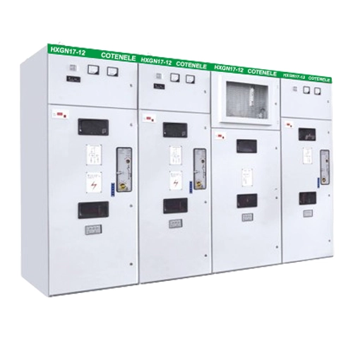
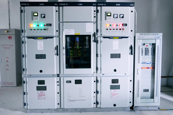
The medium voltage switchgear is the control point for all of these power flows. It can connect or isolate each feeder individually. It can protect each feeder from faults. It can split the bus into separate sections to improve reliability. And it provides the measurement and monitoring points that the facility's operators use to understand what their electrical system is doing at any given moment.
Core Functions of Medium Voltage Switchgear
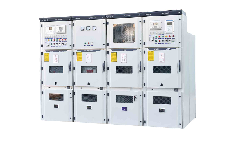
Medium voltage switchgear performs four fundamental functions in a power distribution system. Understanding each one explains why the equipment is designed the way it is.
Function One: Switching Under Normal Conditions
The most basic function of any switchgear is to connect and disconnect circuits under normal load. A feeder to a production line needs to be energized when the line is running and de-energized for maintenance. A generator circuit breaker needs to close when the generator is brought online and open when it is taken offline. A bus coupler needs to connect two sections of busbar when a transformer is taken out of service and the remaining transformer must supply both sections.
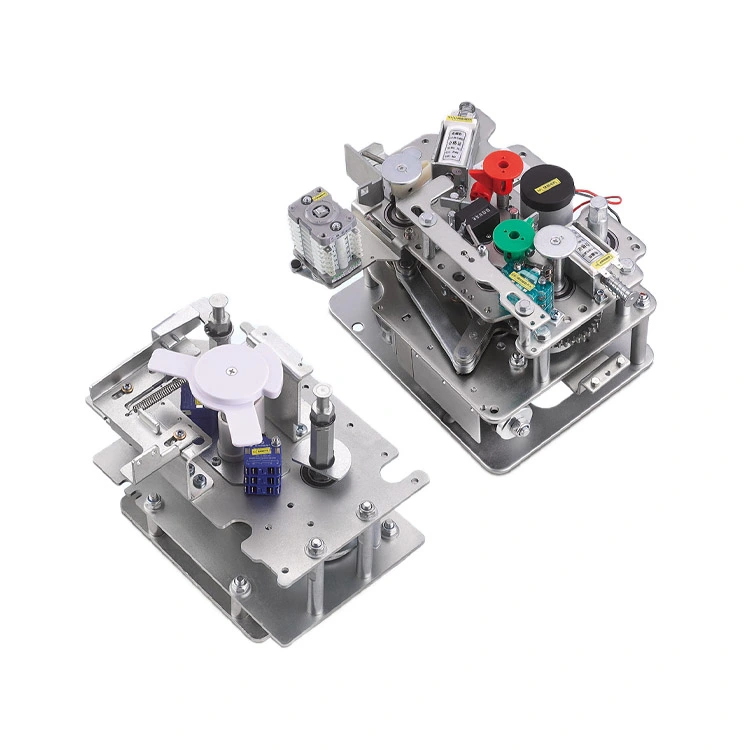
These switching operations are routine, but they are not trivial. The switching device must be able to interrupt the full load current without excessive arcing or contact erosion. It must be able to perform this operation thousands of times over its service life. And it must do so in a way that does not compromise the safety of the operator standing in front of the panel.
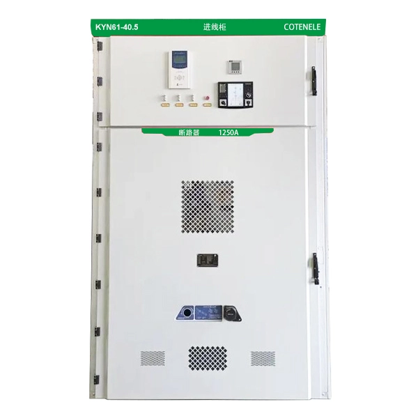
Vacuum circuit breakers handle this duty for most medium voltage applications today. The vacuum interrupter extinguishes the arc inside a sealed ceramic bottle where there is no gas to ionize, no oil to degrade, and nothing to maintain. For applications with lower switching frequency, load break switches—which are simpler and less expensive than full circuit breakers—may be used for feeders that are not expected to interrupt fault current.
Function Two: Fault Protection
If switching under normal conditions is the routine work of switchgear, fault protection is its critical mission. A fault—a short circuit between phases, or between a phase and ground—can release energy on a scale that is difficult to visualize. The current at the fault point can rise to tens of thousands of amperes in milliseconds. The thermal and mechanical forces generated by this current can destroy equipment, start fires, and injure personnel.
The switchgear must detect the fault, interrupt the current, and isolate the faulted section before any of these consequences occur. This requires three things to work together: a protection relay that senses the abnormal current, a circuit breaker that can interrupt it, and a system design that limits collateral damage to healthy parts of the network.
Medium voltage protection relays have become increasingly sophisticated. Modern numerical relays can distinguish between different types of faults, discriminate between faults on their protected feeder and faults downstream, and record waveform data that helps engineers understand what happened after the event. But the relay can only send a trip signal. The circuit breaker must then physically separate its contacts against the full electromagnetic forces of the fault current, extinguish the arc that forms between them, and recover its dielectric strength fast enough to prevent re-ignition. This is what a vacuum circuit breaker with a rated short-circuit breaking current of 25 kA or 31.5 kA is designed and tested to do.
Function Three: Isolation for Safety
Fault protection clears dangerous conditions automatically. Isolation is a deliberate action taken to make equipment safe for people to work on.
When a maintenance team needs to access a transformer, a cable termination, or a circuit breaker itself, they need a visible, verifiable break in the circuit. They need to know that the circuit cannot be re-energized accidentally. And they need the equipment to be connected to earth so that any residual or induced voltage cannot present a hazard.
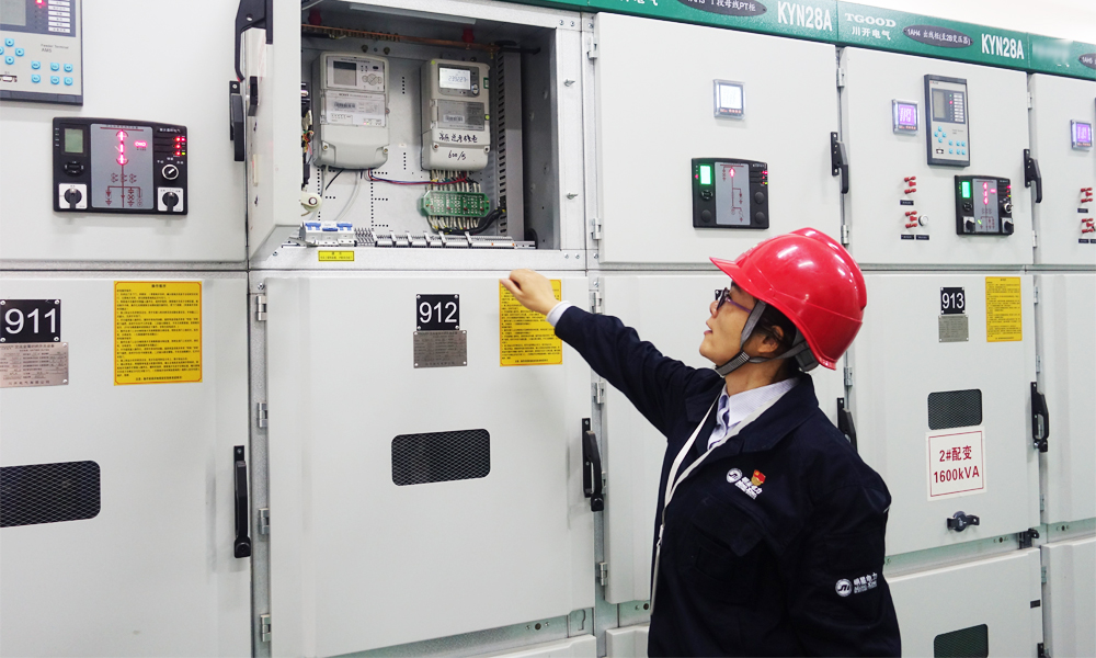
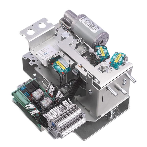
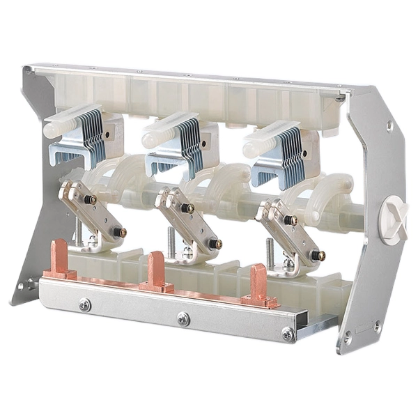
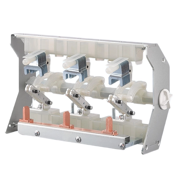
Medium voltage switchgear provides this through the combination of circuit breakers, disconnectors, and earthing switches, all interlocked so that operation must follow a safe sequence. The operator must open the circuit breaker first, then open the disconnector to create a visible isolation gap, then close the earthing switch to ground the isolated section. The mechanical interlocks prevent any of these steps from being performed out of order. This is the "five prevention" interlocking system that is standard on all modern medium voltage switchgear.
Function Four: Measurement and Monitoring
No distribution system can be managed without data. Current measurements tell the protection relays what the system is doing. Voltage measurements enable power quality monitoring and synchronisation checks. Energy measurements are the basis for billing and cost allocation. And increasingly, condition monitoring data from the switchgear itself—temperature, partial discharge, mechanism travel time—is used to predict when maintenance is needed before a failure occurs.
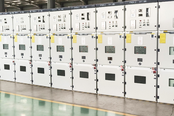
Medium voltage switchgear integrates all of these measurement functions. Current transformers and voltage transformers are mounted in the cable compartment or on the busbars. Their secondary outputs are wired to protection relays, meters, and transducers in the low voltage compartment. In modern installations, these devices communicate via digital protocols such as IEC 61850, Modbus, or Profibus to the facility's central SCADA or energy management system. The switchgear panel is both a power device and a data source.
Switchgear Configurations in Distribution Systems
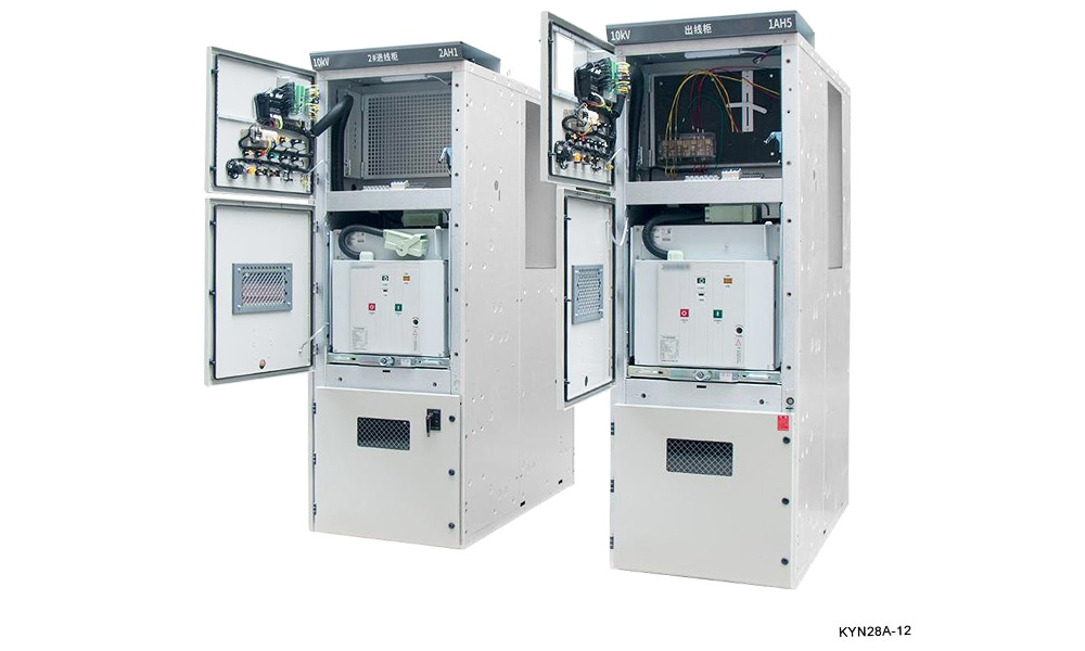
The physical arrangement of switchgear panels in a distribution system is not arbitrary. It reflects the operational philosophy of the facility and the reliability requirements of the loads being served.
Single Busbar
The simplest configuration is a single busbar with all incoming and outgoing feeders connected to it. A single transformer supplies the bus. If the transformer fails or is taken out of service for maintenance, all loads on that bus lose power. This configuration is low in cost and simple to operate, but it offers no redundancy. It is used where the consequence of a supply interruption is tolerable—a small commercial building, a non-critical industrial process, or a temporary construction supply.
Sectionalized Single Busbar
Adding a bus section circuit breaker creates two busbar sections that can operate independently or be coupled together. Each section is supplied by its own transformer. If one transformer fails, the bus coupler closes and the healthy transformer supplies both sections. The loads experience a brief interruption during the transfer, but service is restored quickly. This is the most common configuration for medium-sized industrial plants and commercial facilities where some downtime is acceptable for maintenance but total loss of supply is not.
Main-Tie-Main
A main-tie-main configuration places a bus coupler between two separate bus sections, each with its own main incoming breaker and transformer. The coupler is normally open. If either transformer is lost, the coupler closes automatically or through operator action. This configuration offers higher reliability than a simple sectionalized bus because the coupler operation can be automated and the transfer can occur without any operator intervention. It is used in critical facilities such as hospitals, data centers, and continuous-process industrial plants.
Ring Main Unit (RMU) Configuration
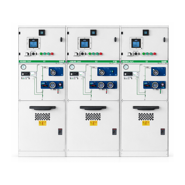
For distribution networks that serve multiple geographically dispersed loads—a university campus, an urban distribution network, a wind farm collector system—the ring main unit configuration is the standard solution. Several RMU panels are connected in a ring, with each panel typically containing two load break switches for the ring feeders and one circuit breaker or fused switch for the local transformer. Power can flow in either direction around the ring. If a cable fault occurs anywhere on the ring, the two RMU panels adjacent to the fault can isolate the damaged section, and all other loads continue to receive power from the healthy side of the ring. This architecture provides a level of supply reliability that a radial system cannot match, at a cost that is far lower than duplicating the entire supply infrastructure.
COTENELE supplies 24 kV SF₆-free RMUs for ring main applications, using dry air as the insulating medium in a sealed-for-life stainless steel tank. The RMU modules—incoming, outgoing, transformer protection, bus coupler, and direct metering—are built from standardized, type-tested subassemblies that can be configured to match the project single-line diagram.
The Transition to SF₆-Free in Distribution Switchgear
An important development in medium voltage switchgear over the past decade has been the shift away from SF₆gas as an insulating and arc-quenching medium. This is particularly relevant to gas-insulated switchgear and ring main units, where SF₆was traditionally used to fill the sealed tank that encloses all live parts.
The driver for this transition is environmental regulation, most notably the EU F-gas Regulation that now prohibits new SF₆switchgear up to 24 kV on the European market. But the transition is also supported by sound engineering logic. Dry air and nitrogen have zero global warming potential, require no special handling at end of life, and eliminate the administrative burden of F-gas record-keeping and leak reporting. Vacuum interruption, which has been the standard for circuit breaker applications for decades, provides the arc-quenching function without any gas at all.
For a facility operator, the practical difference between an SF₆RMU and a dry air RMU is minimal in terms of electrical performance—both are type-tested to the same IEC 62271-200 standard. The difference shows up in operational procedures. A dry air RMU with a sealed-for-life tank has no gas pressure to monitor, no refilling schedule to maintain, and no end-of-life gas recovery to arrange. For a utility or industrial operator managing hundreds of substations, this simplification has real value.
Designing a Distribution System: The Switchgear Specification
For engineers who specify medium voltage switchgear, several decisions define the final system configuration.
Voltage and fault level. The system voltage determines the dielectric design of the switchgear. The available fault current determines the required short-circuit breaking capacity. Both are established by the upstream grid connection and the transformer impedance. Underspecifying the fault rating is dangerous. Overspecifying it adds unnecessary cost. The right number comes from a short-circuit study.
Busbar configuration. The choice between single busbar, sectionalized busbar, and main-tie-main configurations depends on the reliability requirement and the budget. Higher reliability configurations add panel count, cost, and complexity, but they protect against the single most common cause of extended outages: transformer failure.
Circuit breaker versus fused contactor. For feeders supplying transformers, a circuit breaker provides both overload and short-circuit protection. For feeders supplying motors, a fused contactor may be more economical and provide better protection against motor-specific fault conditions. The decision depends on the load type and the required level of protection coordination.
Fixed versus withdrawable. Fixed switchgear is simpler and lower in cost, but any maintenance on the circuit breaker requires de-energizing the entire bus section. Withdrawable switchgear allows a breaker to be racked out for maintenance while the bus remains energized. For critical facilities where downtime is extremely expensive, the withdrawable configuration is usually justified.
Integration and communication. The switchgear must interface with the facility's protection and control system. The communication protocol, the type and quantity ofcurrent and voltage transformers, and the auxiliary power supply for protection relays and control circuits must all be defined in the specification.
Related News
- Smart Ring Main Units: Key Trends in Medium-Voltage Distribution Networks
- 24kV SF6-Free Switchgear Gains Momentum as Medium-Voltage Distribution Moves Toward Low-Emission Technologies
- How Can Medium Voltage Switchgear Improve Power Distribution Safety and Efficiency?
- How Does a Cable Distribution Box Improve Cable Management and Electrical Safety?
- How Low Voltage Switchgear Improves Electrical Safety and Power Management?
- How Does a Ring Main Unit Improve Power Distribution Reliability?
Leave me a message