
News
How Does a Gas Insulated Switchgear (GIS) Work?
Introduction: The Metal Box That Controls Thousands of Volts
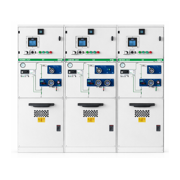
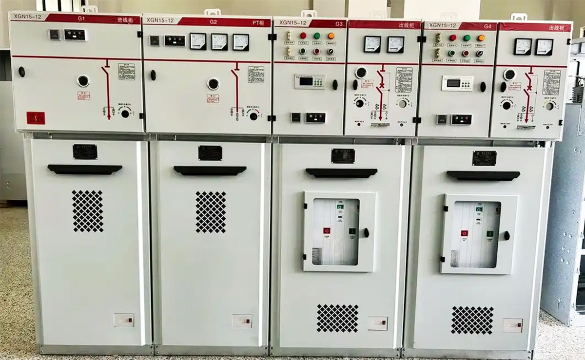
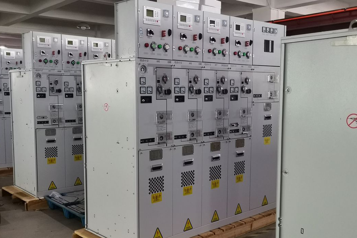
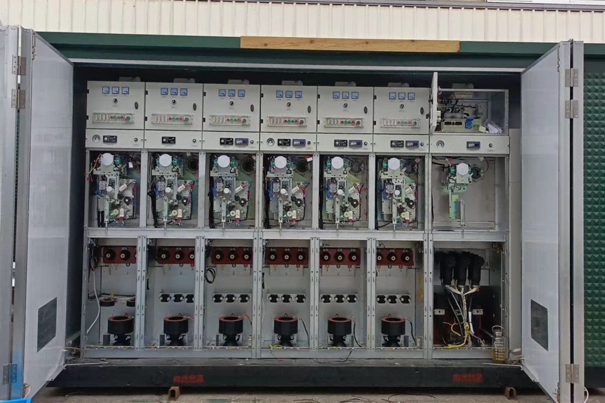
Walk into any modern substation, wind farm collector platform, or the basement of a city skyscraper, and you will find a row of unassuming metal cabinets quietly doing one of the most dangerous jobs in the electrical world. These are gas insulated switchgear panels—or GIS—and they are designed to contain, control, and extinguish electrical arcs that would otherwise vaporize metal and endanger anyone nearby.
For an electrical engineer, understanding how a GIS works is not an academic exercise. It determines how a substation is laid out, how maintenance is scheduled, and whether the equipment will still be operating reliably thirty years after it was commissioned. For a procurement professional, it clarifies why one panel costs more than another and what that extra investment buys in terms of safety, footprint, and lifecycle cost.
This article explains, component by component, how a gas insulated switchgear functions—from the sealed gas tank that keeps high-voltage conductors apart, to the vacuum interrupter that breaks the circuit, to the mechanical interlocks that prevent a dangerous mistake from becoming a fatality.
What Exactly Is a Gas Insulated Switchgear?
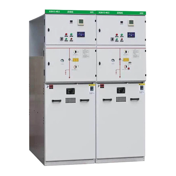
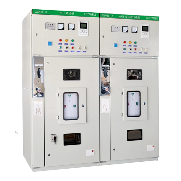
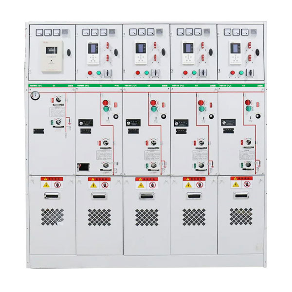
A gas insulated switchgear is a metal-enclosed switchgear where the primary medium voltage components—busbars, circuit breakers, disconnectors, earthing switches, and instrument transformers—are housed inside a sealed, gas-filled compartment. The gas acts as the insulating medium between live parts and between live parts and earth.
Traditional air-insulated switchgear relies on physical distance: conductors are spaced far enough apart that the surrounding air can withstand the voltage stress without breaking down. Gas insulated switchgear replaces that physical distance with a pressurized gas that has far higher dielectric strength than air. This allows the entire assembly to be shrunk dramatically—in some cases, a GIS occupies less than a quarter of the floor area of an equivalent air-insulated installation.
The gas tank itself is typically made of stainless steel or aluminium alloy, welded and sealed to prevent gas leakage over the equipment’s service life. Inside, the atmosphere is controlled and monitored. Modern designs increasingly use dry air or nitrogen instead of SF₆, a response to regulations that are reshaping the industry.
How a GIS Panel Is Built: The Internal Architecture
Although a GIS appears from the outside as a single metal cabinet, internally it is divided into several functional compartments, each isolated from the others by gas-tight barriers or bushings. Understanding these compartments explains how the equipment achieves both operational flexibility and safety.
1. The Busbar Compartment
The busbar is the backbone of any switchgear assembly. In a GIS, the busbars run horizontally through a dedicated gas compartment at the top or rear of the panel. Because the busbar connects adjacent panels together, the busbar compartments of multiple panels are often connected via gas-tight bushings, forming a continuous gas zone across an entire switchboard.
The busbars carry the full rated current of the installation—often 1250 A, 2000 A, or higher—and must do so without exceeding temperature limits that would degrade insulation or accelerate contact oxidation. In a GIS, the surrounding gas helps conduct heat away from the busbar conductors, enabling higher current ratings in a smaller cross-section than air insulation would permit.
2. The Circuit Breaker Compartment
If the busbar is the backbone, the circuit breaker is the muscle. It is the device that must interrupt the circuit when a fault occurs—and the demands placed on it are extreme. A medium-voltage circuit breaker may be required to interrupt 25,000 amperes or more, extinguishing an arc that reaches temperatures comparable to the surface of the sun, all within a few milliseconds.
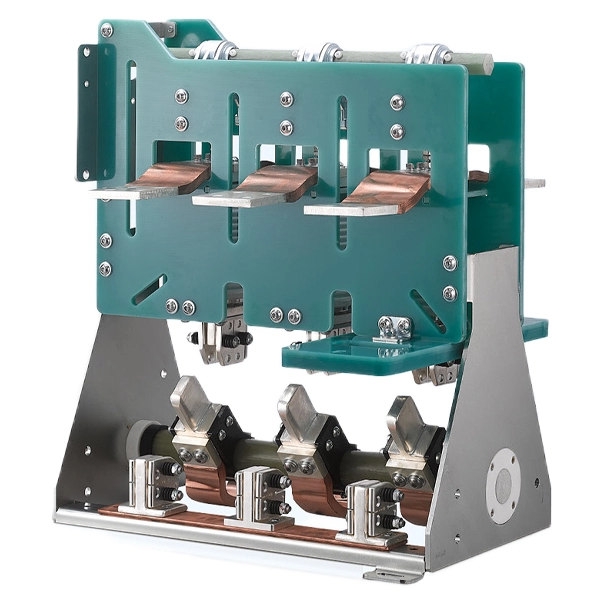
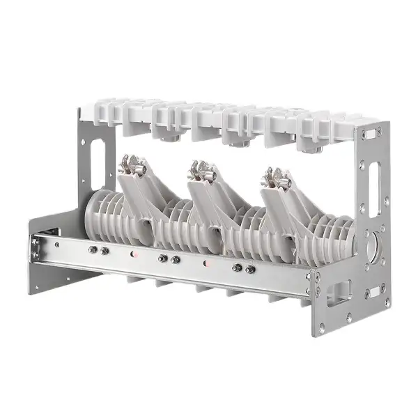
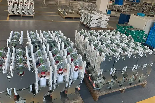
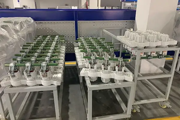
In modern GIS designs, the circuit breaker function is almost universally performed by a vacuum interrupter. The vacuum interrupter is a sealed ceramic bottle with a pair of contacts inside—one fixed, one movable. When the contacts separate, the arc that forms is drawn in a near-perfect vacuum. Because there is virtually no gas to ionize, the arc extinguishes at the first current zero crossing. The surrounding gas in the GIS tank provides the dielectric insulation between the interrupter and the tank wall, but it plays no role in arc quenching.
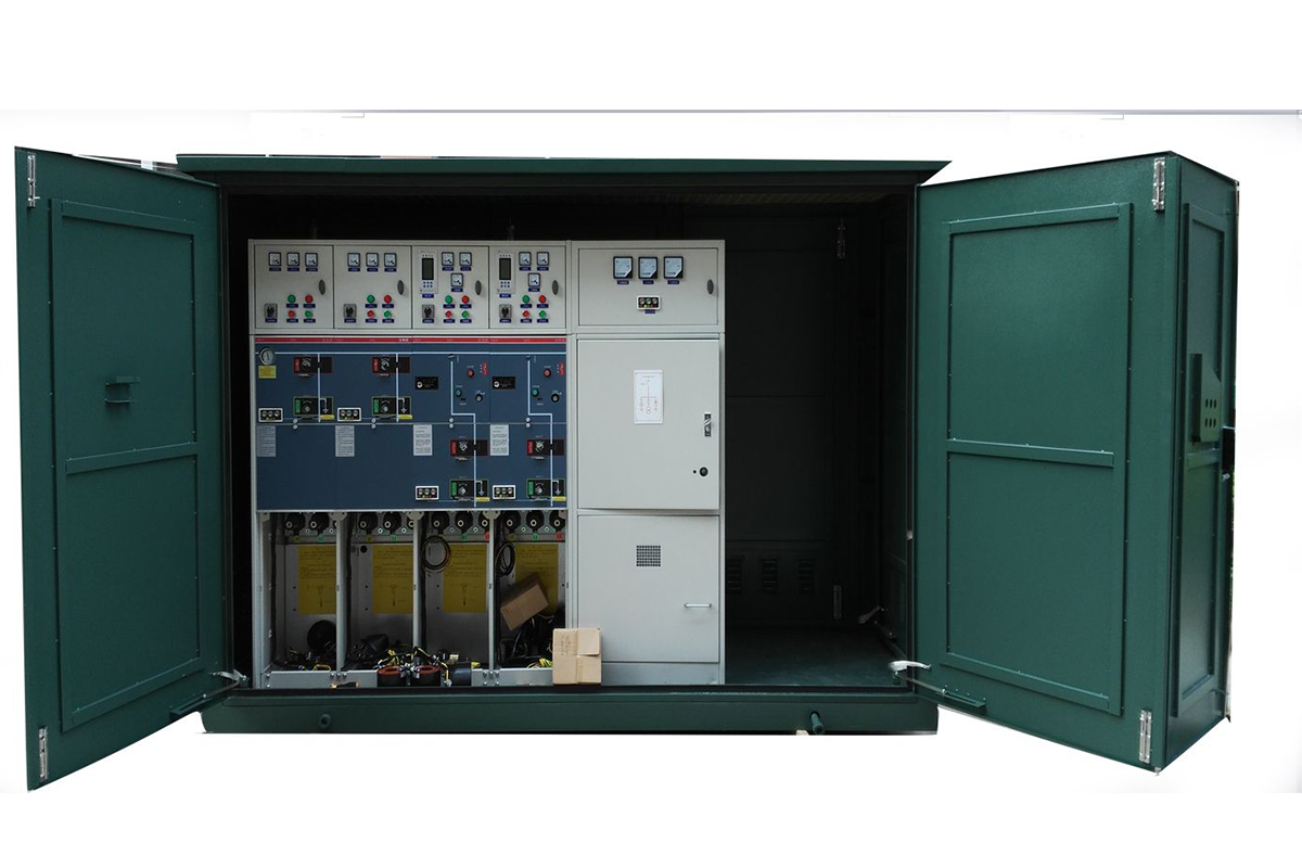
COTENELE’s GIS panels use vacuum circuit breakers rated up to 25 kA or 31.5 kA, with mechanical endurance of 10,000 operations. The vacuum interrupter is maintenance-free for life—no oil, no gas, nothing to replenish.
3. The Disconnector and Earthing Switch Compartment
A circuit breaker can interrupt current, but it cannot provide a visible isolation gap that maintenance personnel can trust with their lives. That function belongs to the disconnector (also called an isolator). The disconnector has no arc-quenching capability—it can only be operated after the circuit breaker has already interrupted the current. Its job is to create a physical air or gas gap that is visibly, mechanically, and electrically certain.
Earthing switches perform the opposite function: they deliberately connect the isolated conductors to earth, discharging any residual capacitive or induced voltage. This is the step that makes the equipment safe to touch.
In a GIS, the disconnector and earthing switch are integrated into a single three-position switch in many designs. One position is “closed” (connected to the busbar), one is “open” (isolated), and one is “earthed.” This three-position design simplifies the mechanical interlocks and reduces the number of gas seals required.
4. Instrument Transformers and Cable Compartment
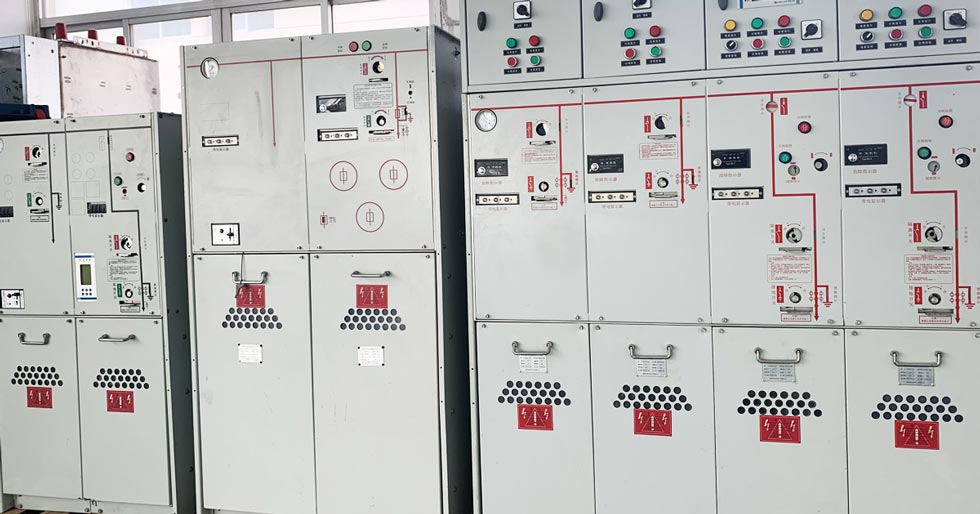
No GIS is complete without measurement. Current transformers (CTs) and voltage transformers (VTs) provide the signals that protection relays, meters, and SCADA systems need to monitor and control the power system. In a GIS, CTs are often toroidal cores mounted around the bushing where the circuit breaker connects to the cable compartment. VTs may be inductive or capacitive, connected to the busbar or feeder side depending on the protection and metering scheme.
The cable compartment is where the external high-voltage cables enter the panel and connect to the internal conductors. In an SF₆-free GIS using dry air, the cable compartment is part of the same sealed gas volume as the switchgear, or separated by a gas-tight bushing, depending on the design. Cable terminations are typically plug-in type, using elastomeric connectors that provide a fully insulated, fully shielded interface between the cable and the switchgear.
5. The Low-Voltage Control Compartment
Behind the front panel door sits the intelligence of the GIS: protection relays, control switches, terminal blocks, auxiliary contactors, and communication gateways. This compartment is at ground potential and is isolated from the high-voltage gas compartments by sealed bushings. All secondary wiring—for tripping, closing, indication, and communication—is routed here.
The quality of workmanship in the low-voltage compartment is a reliable indicator of the manufacturer’s overall quality. Neatly routed wiring, clearly labelled terminals, and properly configured protection relays suggest that similar care has been taken in the parts of the panel the customer cannot easily inspect.
The Physics of Gas InsulationWhy use gas at all?
The answer lies in a fundamental property of matter: dielectric strength.
Every insulating material—air, oil, solid epoxy, or gas—has a limit to the electric field it can withstand before it breaks down and conducts. For air at atmospheric pressure, that limit is approximately 3 kV per millimetre. For SF₆ at a modest pressure, it is roughly three times higher. This means that conductors inside an SF₆-filled tank can be placed much closer together than they could in air, without risk of flashover. The entire switchgear panel shrinks as a result.
The mechanism is molecular. SF₆ is an electronegative gas: its molecules readily capture free electrons, forming heavy negative ions that move slowly in an electric field and are poor at sustaining an electron avalanche. This property gives SF₆ both its high dielectric strength and its excellent arc-quenching ability.
Dry air and nitrogen work on a simpler principle. Their dielectric strength is lower than SF₆ at the same pressure, but it is sufficient for medium-voltage applications when the tank geometry is designed with appropriate clearances. The trade-off is a slightly larger tank volume for the same voltage rating, an engineering compromise that most manufacturers and users now accept as the price of eliminating SF₆’s global warming potential of 23,500 times that of CO₂.
How the Interlocks Work
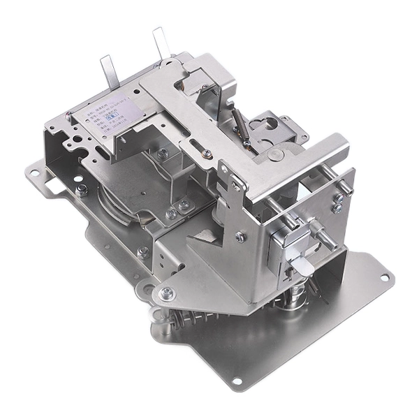
One of the defining features of a GIS is its mechanical interlocking system, often called the “five-prevention” interlock. These interlocks are purely mechanical—they do not depend on electrical power, software, or human memory.
The logic is simple but unforgiving:
1.The circuit breaker cannot be closed unless the disconnector is fully open or fully closed.
2.The disconnector cannot be operated while the circuit breaker is closed.
3.The earthing switch cannot be closed while the circuit is energized.
4.The circuit breaker cannot be closed while the earthing switch is engaged.
5.The cable compartment door cannot be opened unless the earthing switch is closed.
These rules are enforced by cams, levers, and sliding bolts that physically block the operating handles or the door latch when the conditions are not satisfied. For an operator standing in front of the panel, this means that an unsafe sequence of actions is not merely prohibited—it is mechanically impossible.
SF₆-Free GIS: Same Principle, Safer Gas
The operating principle of an SF₆-free GIS is identical to that of a conventional SF₆ GIS. The same compartments, the same vacuum interrupter, the same disconnector and earthing switch, the same interlocks. The only thing that changes is the gas inside the sealed tank.
COTENELE’s medium-voltage GIS uses dry air as the insulating medium. The gas is purified, dehumidified, and sealed inside a stainless steel tank at the factory. The tank is tested for leaks and then left sealed for its entire 30-year design life. There is no pressure gauge for an operator to read, no refilling port, and no gas-related maintenance procedure to follow. The gas system is, from the user’s perspective, invisible.
This approach has three practical advantages for the end user:
- Environmental compliance. No SF₆ means no F-gas reporting obligations, no leak detection program, and no end-of-life gas recovery. The equipment complies with the EU F-gas Regulation without exceptions or workarounds.
- Simplified maintenance. A maintenance technician who opens the panel door finds the same vacuum circuit breaker, the same disconnector mechanism, and the same protection relays as in any other modern GIS. There is no gas handling equipment to understand.
- Future-proofed investment. As SF₆ restrictions tighten globally, equipment that does not contain SF₆ will not face tightening service restrictions, rising gas costs, or mandatory retrofit requirements.
Where GIS Is Used
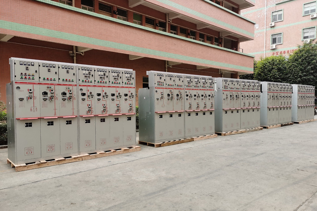
GIS technology is deployed wherever space is constrained, reliability is critical, or environmental conditions make air-insulated equipment impractical:
- Urban substations where real estate costs make compact equipment a financial necessity.
- Wind farm collector substations where switchgear must operate reliably in remote, sometimes harsh environments with limited maintenance access.
- Data centers where uptime guarantees and ESG commitments demand SF₆-free, low-maintenance equipment.
- Industrial plants with corrosive atmospheres, high dust levels, or high humidity that would degrade exposed air-insulated conductors.
- Infrastructure such as airports, metros, and tunnels, where fire safety and compactness are non-negotiable.
Frequently Asked Questions
Q: Can a GIS be repaired if the gas leaks?
A: For a sealed-for-life dry air GIS, the tank is welded and tested at the factory and is not designed to be opened on site. If the tank is ever compromised, the entire panel is typically replaced. This is why tank integrity testing during manufacturing is critical. However, gas leakage from a properly manufactured sealed tank is extremely rare over the equipment’s life.
Q: How do you know the vacuum interrupter is still working?
A: Vacuum integrity is verified during routine factory testing via a high-potential test across the open contacts. In service, vacuum interrupters are maintenance-free and do not degrade over time. The only wear mechanism is contact erosion during fault interruption, which is accounted for in the interrupter’s rated electrical endurance.
Q: Is dry air GIS physically larger than SF₆ GIS?
A: At medium-voltage levels up to 40.5 kV, the size difference is minimal and fits within standard panel dimensions. Manufacturers have optimized tank geometries over years of development to minimise the footprint of dry air designs.
Q: What standards apply to GIS?
A: Metal-enclosed GIS is type-tested to IEC 62271-200. The circuit breaker inside is tested to IEC 62271-100. Internal arc classification (IAC) is tested per IEC 62271-200 annex A. COTENELE provides full type-test certificates from independent IEC-accredited laboratories with every quotation.
Conclusion: Mastery of the Basics
A gas insulated switchgear works by sealing high-voltage conductors in a gas atmosphere that insulates them from each other and from earth, allowing the entire assembly to be made far smaller than its air-insulated equivalent. Inside that sealed environment, vacuum interrupters break the circuit, disconnectors provide visible isolation, earthing switches make the equipment safe to touch, and a network of mechanical interlocks ensures that these operations can only be performed in the correct sequence.
The transition from SF₆ to dry air has not changed this fundamental architecture. It has simply replaced the gas with one that does not carry a millennia-long environmental liability. For engineers and purchasers, understanding how a GIS works is the foundation for specifying the right equipment, verifying manufacturer claims, and ensuring that the switchgear installed today will still be protecting the network three decades from now.
COTENELE manufactures SF₆-free gas insulated switchgear using dry air insulation and vacuum interruption, type-tested to IEC 62271-200. Our engineering team provides complete documentation packages—including type-test certificates and routine test reports—at the tender stage, enabling our customers to specify with confidence.Looking for SF₆-Free GIS for Your Next Project?COTENELE supplies 12 kV to 40.5 kV SF₆-free gas insulated switchgear, ring main units, and vacuum circuit breakers for utility, renewable energy, data centre, and industrial applications.
COTENELE is a specialised manufacturer of medium-voltage switchgear, including SF₆-free gas insulated switchgear, vacuum circuit breakers, ring main units, and metal-clad panels for 12 kV to 40.5 kV applications. Our products serve utilities, data centre operators, renewable energy developers, and industrial buyers across Europe, Asia, and the Middle East.
Related News
- Smart Ring Main Units: Key Trends in Medium-Voltage Distribution Networks
- 24kV SF6-Free Switchgear Gains Momentum as Medium-Voltage Distribution Moves Toward Low-Emission Technologies
- How Can Medium Voltage Switchgear Improve Power Distribution Safety and Efficiency?
- How Does a Cable Distribution Box Improve Cable Management and Electrical Safety?
- How Low Voltage Switchgear Improves Electrical Safety and Power Management?
- How Does a Ring Main Unit Improve Power Distribution Reliability?
Leave me a message