Products
High Quality Power Transformer from China Manufacturer with IEC Standards
Cotenele is important supplier of transformers for State Grid Corporation of China. We have long-term cooperation in many large substations and distribution projects. Cotenele power transformers typically voltage ratings include 10 kV, 20 kV, and 35 kV, and come in both oil-immersed and dry-type types based on insulation medium, they are suitable for indoor and outdoor, main applications ranging from distribution networks to industrial substations. The transformers manufactured by Cotenele comply with international and national standards, such as IEC 60076 series, IEEE C57.12, GB/T 1094 series, GB 20052, and the power industry standard DL/T 572. Cotenele transformers can also be equipped with optional features such as on-load tap changers and intelligent online monitoring systems, which can meet specific grid requirements and enhance reliability.
- View as
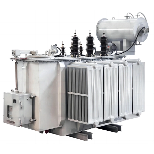
33KV Oil Immersed Electrical Distribution Transformer
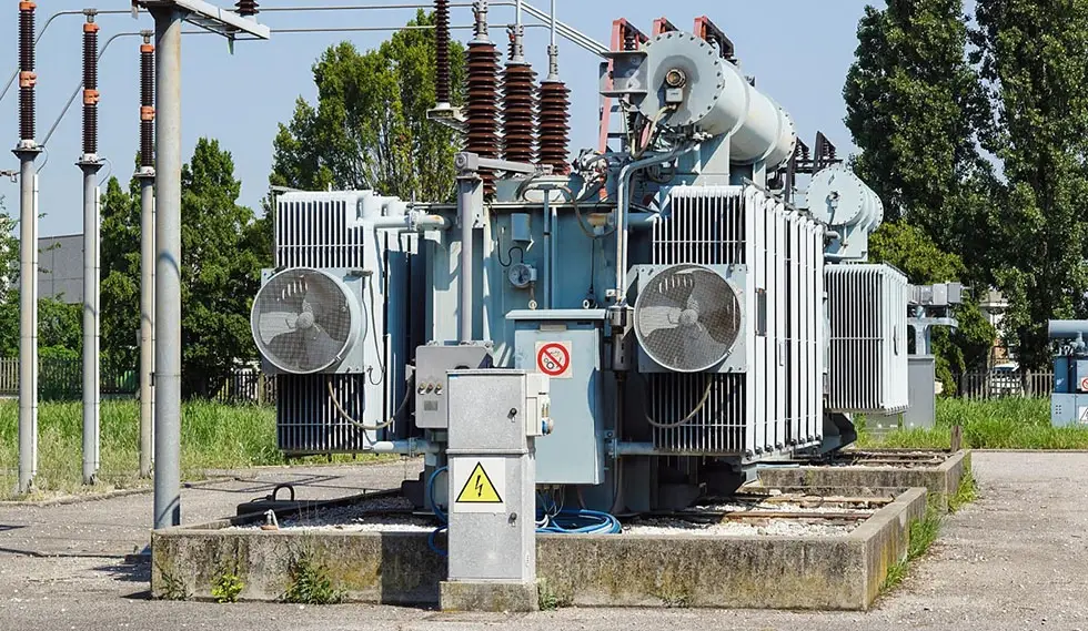
The 33KV Oil Immersed Electrical Distribution Transformer is one of Cotenele's main products, and we are a large transformer manufacturer and exporter in China. The 33KV Oil Immersed Electrical Distribution Transformers reduce the voltage of the 35kV network to the low voltage (usually 400V) bus voltage used by users, and is an important equipment for connecting the high-voltage transmission network and the low-voltage distribution network. The 35KV transformer produced by Cotenele has excellent insulation performance, good heat dissipation effect, and low price. It is widely praised by customers in the overseas market,especially in Africa.
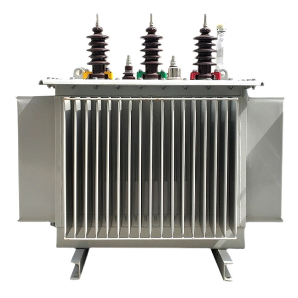
20KV Oil Immersed Type Electrical Transformer
Cotenele is a large electrical transformer manufacturer and exporter from China. Over the years, we have provided a large number of high-quality electrical transformer products to domestic and overseas customers. The 20KV Oil Immersed Type Electrical Transformer we produced have reliable quality and stable performance, and have received widespread praise from customers over the years. All of the power transformers we produced comply with relevant standards such as IEC60076, GB/T 6451-2023, GB 1094, etc
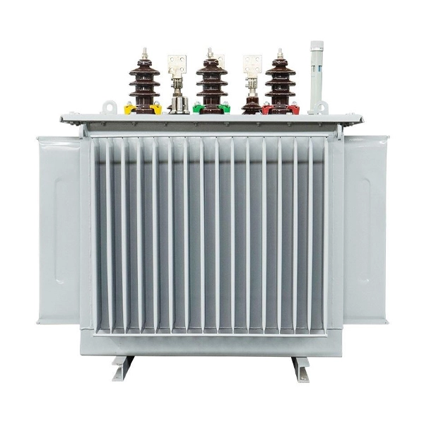
10kV Oil Immersed Distribution Power Transformer
Cotenele is a manufactuer and exporter of Power Transformer located in "Electrical Capital of China"-Liushi Town,Yueqing city,Wenzhou city.Our 10kV Oil Immersed Distribution Power Transformer is widely severing in the power distribution system,such as urban and rural distribution networks, industrial and mining enterprises, commercial complexes, and other multiple application scenarios.
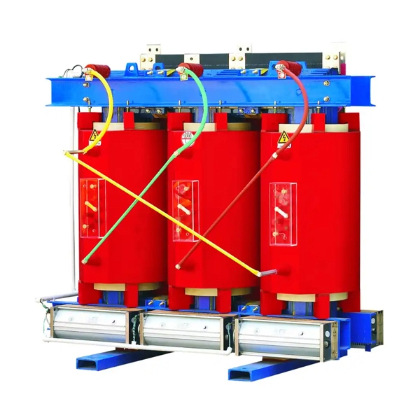
36KV Dry Type Power Transformer
Cotenele is one of the important partners of State Grid Corporation of China, and our 36KV Dry Type Power Transformer has been operating stably in the national power system for a long time.
Cotenele 36kV series dry-type power transformer has passed the appraisal and testing of the National Machinery Industry Bureau and the State Power Company, and is mainly used in urban and rural power grids, other industries, mining enterprises, power transmission and distribution industries, and agricultural projects.
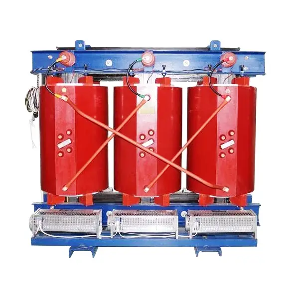
20KV Dry Type Electriacl Distribution Transformer
Cotenele is a large manufacturer and exporter for 20KV Dry Type Electriacl Distribution Transformer from China,our 20KV dry-type transformers have features of longer power supply radius, lower voltage drop, reduced line losses, and less consumption of non‑ferrous metals.These 20 kV dry‑type transformers are increasingly used in high‑rise buildings, commercial centres, petrochemical plants, mines, power plants, airports, and many other locations.
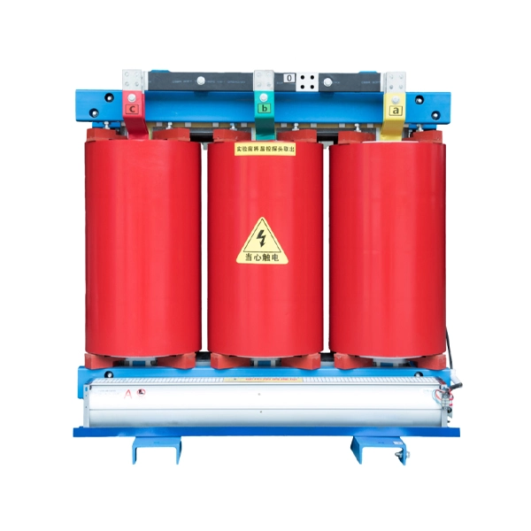
10KV Indoor Dry Type Power Distribution Transformer
Cotenele is a manufacturer and exporter of transformers and other electrical equipment, as well as core components. Our 10KV Indoor Dry Type Power Distribution Transformer are sold to multiple overseas markets such as Europe, the Middle East, Africa, and South America. Dry-type transformers have the advantages of small size, no pollution, and no maintenance, and are important electrical equipment in distribution systems.
What is a transformer?
Transformer is an electrical device that uses the principle of electromagnetic induction to change the voltage of alternating current, usually including step-up and step-down transformers. In the process of set-up and set-down voltage the transformers will keep its frequency unchanged, by varying the turns ratio between the primary and secondary windings. Its core operating mechanism is that when AC flows through the primary winding, it creates a varying magnetic field in the core, which in turn induces an electromotive force in the secondary winding, thereby enabling the conversion between voltage and current: stepping up voltage reduces current, stepping down voltage increases current, and ideally the total power remains constant. This characteristic makes it possible to greatly reduce transmission losses in long-distance power delivery, while also providing safely adapted voltages for various devices at the point of use. Typical applications range from giant transformers in substations, distribution transformers on utility poles, to miniature transformers inside mobile phone chargers. However, it is need to note especially that a transformer works only with alternating current and cannot convert direct current.
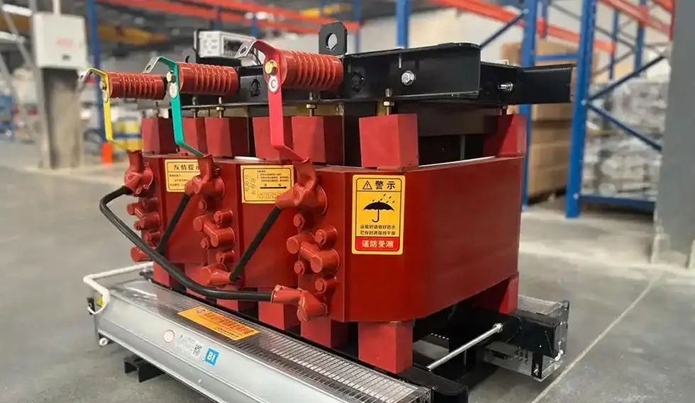
What is the working principle of a transformer?
The working principle of a transformer is based on the law of electromagnetic induction. When an AC current flows through the primary winding, it creates an alternating magnetic flux in the core. This alternating flux simultaneously links both the primary and secondary windings, inducing an electromotive force (EMF) in each winding. Through this electromagnetic induction, the transformer transfers electrical energy and transforms the voltage, with only magnetic coupling between the two windings and no direct electrical connection.
The voltage transformation relationship is:
U₁/U₂ = N₁/N₂ = k
where U₁, U₂ are the primary and secondary voltages, N₁, N₂ are the number of turns in the windings, and k is the turns ratio. When the secondary has more turns than the primary, the transformer steps up voltage; when it has fewer turns, it steps down voltage.
Construction and Key Components
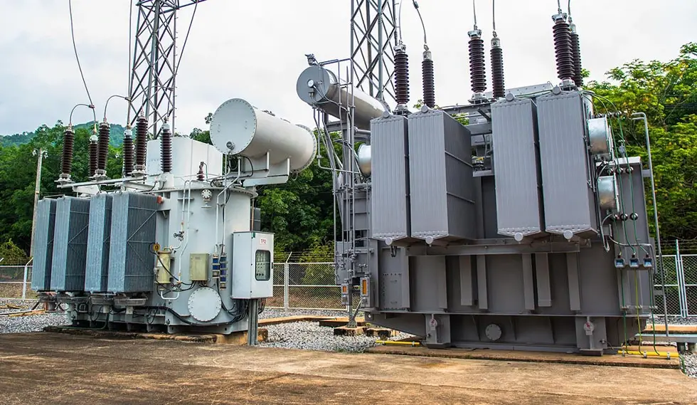
A transformer mainly consists of the active part such as core, windings, insulation, and leads, tank, cooling system, protective devices, and bushings. The core and windings which also called coils, are the most essential components.
1. Core (Magnetic Circuit)
The core provides the magnetic path and is composed of core legs (vertical sections on which the windings are mounted) and yokes (horizontal sections that close the magnetic path). To reduce eddy current losses and hysteresis losses, the core is typically built from stacked silicon steel laminations, each coated with insulating varnish or an oxide layer to insulate them from each other. Core configurations are mainly core-type (windings surround the core legs, common in power transformers) and shell-type (core surrounds the windings, resulting in low leakage flux and high mechanical strength, often used in precision instruments and small devices).
2. Windings (Electrical Circuit)
Windings are the electrical circuit of the transformer, divided into primary winding and secondary winding. They are made of copper or aluminum wire with high-strength insulation. The windings are usually arranged concentrically (low-voltage winding placed next to the core leg, high-voltage winding wound around the outside). Regarding insulation, modern oil-immersed transformers mostly use an oil-paper barrier composite insulation system consisting of pressboard, cable paper, and transformer oil. The thickness of the pressboard is typically 2-5 mm, enabling reliable insulation for high voltage levels.
The above describes the core electromagnetic system, and the following auxiliary systems are also very important for oil-immersed transformers:
Tank: An external container used to hold iron cores, windings, and fill transformer oil. Large capacity transformers are usually equipped with external radiators or cooling pipes to enhance heat dissipation.
Transformer Oil: It serves as both an insulating medium (with better insulation performance than air) and a cooling medium (the heat generated by the transformer core and winding is transferred to the oil tank wall through the convection of oil). According to different pour points, transformer oil is divided into different grades such as 10, 25, and 45 to adapt to different climatic conditions.
Conservator (Oil Surge Tank): A horizontal fuel tank installed above the main fuel tank, connected by pipes. It separates oil from air through a diaphragm. Based on the features of oil expanding and contracting with temperature changes, it stores oil at higher temperatures and supplies oil at lower temperatures, thereby reducing the contact between oil and air and preventing moisture absorption and aging.
Bushings: Lead high and low voltage wires out of the insulated terminals of the transformer casing; They provide electrical insulation and mechanical support.
Protective Devices: Including on load or off load tap changers, Bucher relays (gas relays), explosion-proof exhaust ports (safety exhaust ports), dehydration respirators (silicone respirators), temperature sensing elements, and related instruments. These devices usually can provide the real-time monitoring and comprehensive protection.
Types Of Transformers
Transformers can be classified in below several aspects:
1. According to Application
Power Transformers: Power transformers are mainly used for voltage conversion and power transmission/distribution in power systems, accounting for over 80% of all transformers.
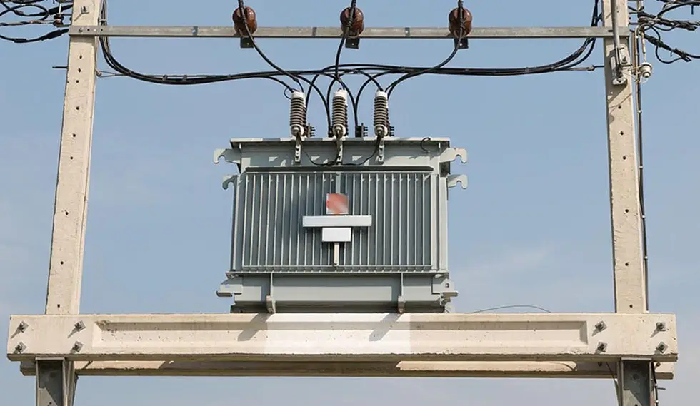
Distribution Transformers: Distribution transformers usually refer to transformers below 35 kV (mainly 10 kV/0.4 kV) that directly supply power to end users.
Special Transformers: Including test transformers for voltage withstand testing, instrument transformers (including voltage transformers, current transformers for measurement and protection), rectifier transformers for AC to DC, used for electrolysis, electroplating, DC drive, furnace transformers, mining transformers, etc.
2. According To Cooling and Insulation Medium
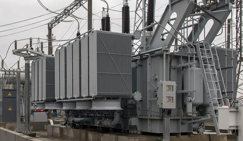
Oil-immersed Transformers: The oil immersed transformer iron core and winding are completely immersed in mineral insulating oil, which has excellent heat dissipation and insulation performance, high efficiency, and relatively low cost. Oil immersed transformers are widely used in outdoor substations and industrial parks, but they require fire and explosion prevention measures.
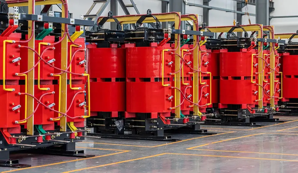
Dry-type Transformers: The dry-type transformers iron core and winding are not immersed in oil; They use air or solid insulation materials such as epoxy resin casting. Dry-type transformers are fire-resistant and leak free, suitable for indoor places with strict fire prevention regulations, such as high-rise buildings, data centers, shopping malls, and hospitals.
Gas-insulated Transformers: Gas-insulated transformers are relatively rare in market, and they generally use synthetic gases such as SF₆ as cooling and insulation media, suitable for special operating conditions.
3. According To Number of Windings
Two-winding Transformer: Two-winding transformers are quite common in power system, which have one high(medium) voltage winding and one low-voltage winding (one primary winding and one secondary winding).
Three-winding Transformer: A three-winding transformer has three windings per phase, connected to different voltage levels (e.g. high-voltage side, medium-voltage side, low-voltage side). This transformer is commonly used in substations which require multiple voltage levels.
4. According To Core/Winding Configuration
Core-type Transformer: The winding of the Core-type transformer surrounds the legs of the iron core (the iron core is surrounded by the winding). This product has a simple structure, low cost, and is widely used in power systems.
Shell-type Transformer: The core of a shell-type transformer surrounds the winding (winding surrounds the core). It has these characteristics such as low leakage flux, high mechanical strength, and compact size and commonly used in precision instruments and small equipment.
5. According To Number of Phases
Single phase transformers used for single-phase loads or for forming three-phase groups and three-phase transformers.
6. According To Voltage Regulation Method
Off-circuit (off-load) Tap Changer (requires de-energizing) and On-load Tap Changer (automatic voltage regulation under load).
7. According To Electrical Connection Type
Isolating (Isolation) Transformer: The primary winding and secondary winding of the isolation transformer are electrically isolated from each other, only through magnetic coupling. This type of transformer has extremely high safety and is commonly used in medical equipment and precision instruments to prevent electric shock and electromagnetic interference.
Autotransformer: Primary and secondary share a portion of the winding, having both magnetic coupling and direct electrical connection. Compact, small size, low losses, but no isolation between primary and secondary. Used for motor starting and voltage regulation (e.g., laboratory variac).
How are power transformers classified?
Rated Capacity (Sn, in kVA or MVA): The apparent power a transformer can deliver continuously at rated voltage and current. It is the most important parameter for selecting a transformer. Chinese capacity grades follow the R10 series, increasing by a factor of 1.26 (100, 125, 160, 200, 250, 315, 400, 500, 630, 800, 1000 kVA, etc.). A reasonable capacity selection first calculates the maximum composite load, then chooses the next higher capacity so that the load factor is about 60-70%, ensuring both long-term safe operation and economy.
Rated Voltage (kV): The primary voltage matches the grid voltage; the secondary voltage is typically 5% or 10% higher than the low-side bus voltage (depending on impedance voltage and capacity) to compensate for line voltage drop and ensure end-user voltage quality.
Short-circuit Impedance (Impedance Voltage, Uk%): The percentage of primary voltage required to circulate rated current through the secondary when the secondary is short-circuited. It is a critical characteristic that affects short-circuit current levels and voltage regulation.
No-load Loss (Po, kW): The active power consumed from the secondary side of a transformer in an open-circuit state at rated frequency and rated voltage is mainly composed of core losses (magnetic losses), which depend on the manufacturing quality and the characteristics of the silicon steel material. If high-performance silicon steel and three-dimensional wound cores are used, the no-load losses can be significantly reduced.
Load Loss (Pk, kW): The active power consumed when the secondary is short-circuited and rated current flows in the primary. It mainly consists of copper loss in the windings and is proportional to the square of the load factor.
Efficiency (η): Output active power divided by input active power. Large power transformers have very high efficiency; for example, a 380 MVA/500 kV generator step-up transformer can achieve η ≥ 99.75%.
Vector Group (e.g., Dyn11, Yyn0): Indicates the connection method (Y -- star, D -- delta, Z -- zigzag) of the high- and low-voltage windings and their phase displacement. It affects the system neutral grounding method and zero-sequence current path.
Cooling Method: E.g., ONAN (Oil Natural Air Natural), ONAF (Oil Natural Air Forced), OFWF (Oil Forced Water Forced). The four-letter codes specify the cooling medium and circulation method (ON: oil natural circulation; OF: oil forced circulation; OD: oil directed forced circulation; AN: air natural; AF: air forced; WF: water forced).
How to choose the suitable transformers?
When selecting a suitable transformer, except determining rated capacity and voltage levels, the following factors should be considered as well:
Load Characteristics: For typical industrial and residential loads, we generally use standard dual-winding power transformers. If multiple voltage levels are required, a three-winding transformer should be selected and the rated capacity of each winding should be allocated reasonably. For places with strict fire safety requirements, such as data centers and high-rise buildings, dry-type transformers should be given priority.
Installation Environment: Oil-immersed transformers with fireproof partitions are usually preferred for outdoor substations, while dry-type transformers should be preferred for indoor use environments.
Capacity Limits: In indoor substations, the maximum capacity of a single oil-immersed transformer should not exceed 1250 kVA; In prefabricated substations, the maximum capacity of oil-immersed transformers should not exceed 630 kVA, and the capacity of dry-type transformers should not exceed 800 kVA.
Voltage Regulation Requirements: For environments with large voltage fluctuations or frequent adjustments, transformers with on-load tap changers are required; For applications with stable voltage, a transformer with no-load tap changer can be used.
Energy Efficiency and Environmental Requirements: Due to energy-saving policies, high-efficiency and energy-saving transformer products are gradually becoming the mainstream choice. At present, the market share of 3D wound iron core transformers (with no-load losses 15%-25% lower than traditional laminated iron cores) and amorphous alloy transformers is increasing year by year.
Special Applications: When voltage regulation is required, an autotransformer should be selected; It is more appropriate to choose an isolation transformer when electrical safety requirements are higher.