Products
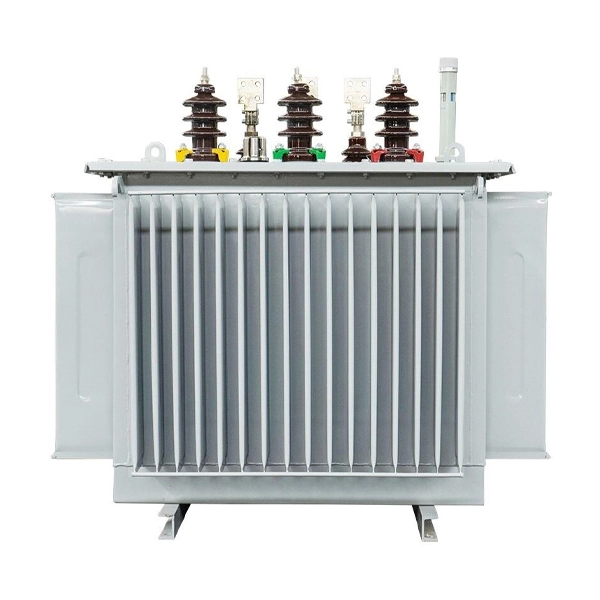
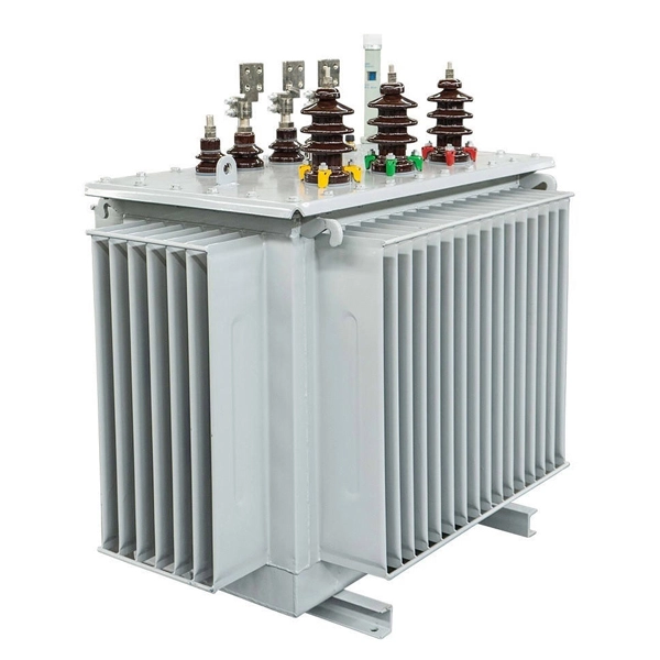
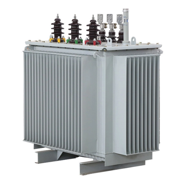
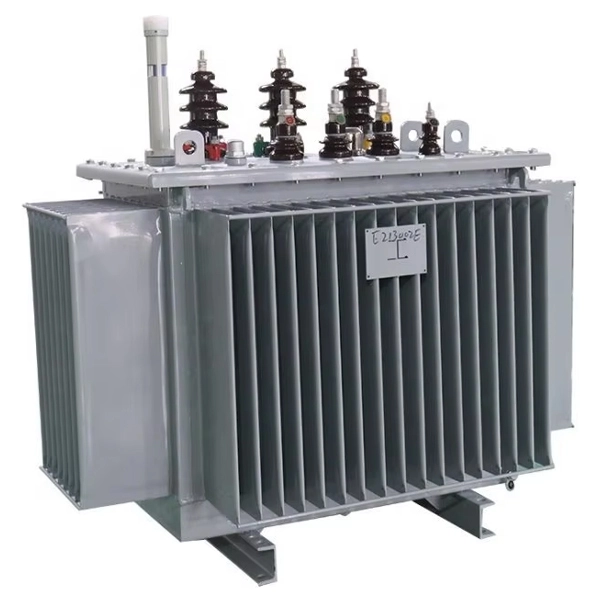
10kV Oil Immersed Distribution Power Transformer
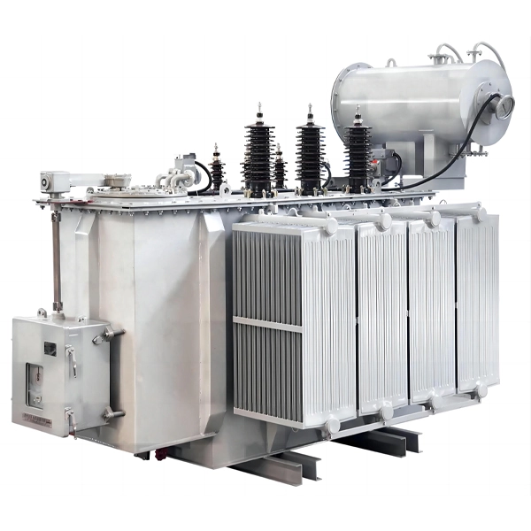
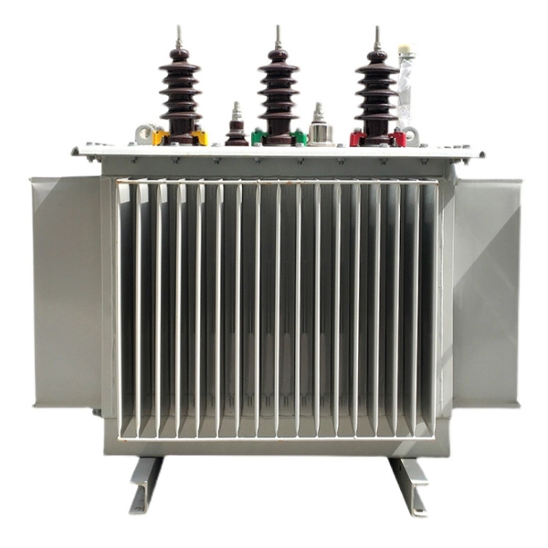
Cotenele is a manufactuer and exporter of Power Transformer located in "Electrical Capital of China"-Liushi Town,Yueqing city,Wenzhou city.Our 10kV Oil Immersed Distribution Power Transformer is widely severing in the power distribution system,such as urban and rural distribution networks, industrial and mining enterprises, commercial complexes, and other multiple application scenarios.
As a manufacturer and exporter of 10kV Oil Immersed Distribution Power Transformer in China, we have provided lot of power transformers to overseas markets such as Europe, Africa, South America, the Middle East etc. The 10KV Oil-immersed transformers use insulating oil as the main insulation medium and also rely on oil as a cooling medium. This power distribution transformer offers outstanding advantages such as low cost, excellent heat dissipation, strong overload capacity, and long service life, making them a long-standing mainstream choice in medium and low voltage distribution scenarios. Our 10kV Oil Immersed Distribution Power Transformer complies with the relevant international standard IEC60076 and native standards GB/T 6451-2023, GB 1094 etc.
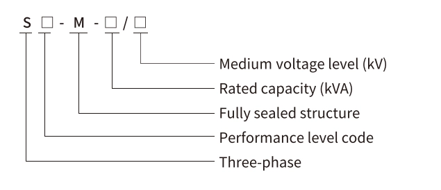
Model and meanings
Standards for 10KV Oil-immersed Distribution Power Transformer
| Standard Category | Standard Name |
| National (GB/T) | GB/T 1094.1-2013 Power transformers – Part 1: General |
| GB/T 1094.2-2013 Power transformers – Part 2: Temperature rise for liquid-immersed transformers | |
| GB/T 1094.3-2017 Power transformers – Part 3: Insulation levels, dielectric tests and external clearances in air | |
| GB/T 1094.5-2008 Power transformers – Part 5: Ability to withstand short circuit | |
| GB/T 1094.10-2003 Power transformers – Part 10: Determination of sound levels | |
| International (IEC) | IEC 60076-1:2011 Power transformers – Part 1: General |
| IEC 60076-2:2011 Power transformers – Part 2: Temperature rise for liquid-immersed transformers | |
| IEC 60076-3:2013+AMD1:2018 Power transformers – Part 3: Insulation levels, dielectric tests and external clearances in air | |
| IEC 60076-5:2006 Power transformers – Part 5: Ability to withstand short circuit | |
| IEC 60076-10:2016 Power transformers – Part 10: Determination of sound levels |
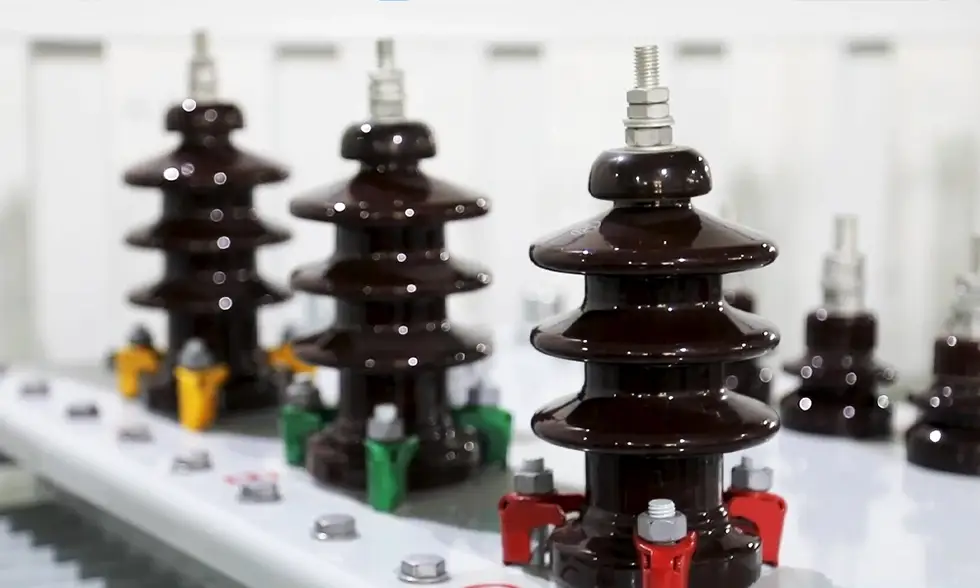
What is a 10KV Oil-immersed Distribution Power Transformer?
A 10kV oil-immersed distribution transformer (commonly referred to as a "distribution transformer") is a static electrical device used in distribution systems to transform AC voltage and current and transmit electrical energy based on the law of electromagnetic induction, with its windings insulated by insulating oil. It generally refers to transformers operating in distribution networks with a voltage class of 10kV, a rated capacity of 6300kVA or below, directly supplying power to end users.
This sort of power transformers are suitable for AC 50/60Hz, three-phase maximum rated capacity up to 2500kVA (single-phase maximum 833kVA, not generally recommended). They can be used indoors or outdoors. Units with capacity ≤315kVA can be pole-mounted. Standard operating conditions: ambient temperature not exceeding 40°C and not lower than -25°C; maximum daily average temperature 30°C; maximum annual average temperature 20°C; relative humidity ≤90% (at 25°C ambient); altitude ≤1000m. If conditions differ from those above, appropriate rating adjustments shall be made according to relevant standards.
Product Structure
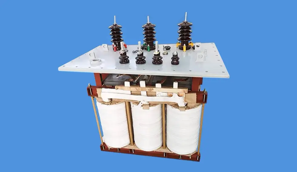
The structure of a 10kV oil-immersed distribution transformer comprises the main body, conservator, insulating bushings, tap changer, protective devices, etc.
1. Main Body
The main body consists of the core, windings, and insulating oil -- the electromagnetic part of the transformer.
Core: The magnetic circuit of the transformer, built from hot-rolled or cold-rolled silicon steel sheets (0.35 or 0.5 mm thick, with insulating varnish on the surface) stacked together. The core consists of core legs (where windings are placed) and yokes (closing the magnetic circuit). Core structures are basically core-type or shell-type, with core-type being most widely used. Some high-end products use a three-dimensional wound core, where the three legs are arranged in an equilateral triangle, resulting in a gapless magnetic circuit, lower losses, and reduced noise.
Windings: The electrical circuit of the transformer, generally wound from insulated flat or round copper wire around a former. The windings are placed on the core legs, with the low-voltage (LV) winding on the inner layer and the high-voltage (HV) winding on the outer layer. Insulating cylinders separate the core from the LV winding and the LV from the HV winding. For LV windings, copper foil cylindrical construction is common (except for very small capacities). HV windings use multi-layer cylindrical construction to balance ampere-turn distribution, reduce stray flux, and provide high mechanical strength and short-circuit withstand capability.
Insulating Oil: Composed mainly of naphthenes, alkanes, and aromatics. It serves two functions: (a) providing insulation between windings, between windings and core, and between windings and tank; (b) dissipating heat by convection when heated. Common types are No.10, No.25, and No.45, where the number indicates the pour point in °C (e.g., No.25 oil solidifies at -25°C). Selection depends on local climate.
2. Tank
The tank is the outer enclosure of the oil-immersed transformer, welded from steel plates. It holds the oil and other components. In medium and small transformers, the tank comprises a case and a cover. The core-and-coil assembly is placed inside the case, and can be lifted out for maintenance after removing the cover. The tank is also fitted with an oil drain valve, earthing screw, nameplate, etc.
3. Conservator (Oil Conservator)
Mounted on top of the tank, the conservator has a volume about 10% of the tank's volume and is connected to the tank by a pipe. As oil expands or contracts with temperature, the conservator supplies or stores oil, ensuring the core and windings remain immersed. It also reduces oil contact with air, slowing oil degradation. A sight glass (oil level gauge) on the conservator shows temperature-calibrated oil levels. The conservator is often fitted with a breather (silica gel dryer) to remove moisture and impurities from incoming air.
4. Insulating Bushings
Bushings are the main insulation components protruding through the tank cover. They bring the HV and LV winding leads out of the tank, provide insulation to ground (tank and core), and fix the external connections. HV bushings are taller, LV bushings shorter.
5. Tap Changer
Mounted on the HV winding, the tap changer changes the number of effective turns to regulate output voltage. When the supply voltage varies, the tap changer adjusts the voltage to maintain a stable secondary voltage. Types: on-load tap changer (can be operated under load) and off-load (no-load) tap changer (requires de-energisation).
6. Protective Devices
Gas (Buchholz) Relay: Installed on the pipe between the tank and conservator -- a primary protection against internal faults. For severe faults, it trips the circuit breaker; for minor faults, it signals an alarm. According to GB/T 6451, transformers ≥800kVA shall be equipped with a Buchholz relay.
Explosion Vent (Pressure Relief Device): Mounted on the tank cover, sealed with a glass diaphragm. If a severe fault occurs and the Buchholz relay fails, the diaphragm bursts to release pressure and prevent explosion.
Thermometer: Monitors top oil temperature. Transformers ≥1000kVA must be equipped with an outdoor signal thermometer, which can be connected to a remote signal.
7. Cooling Equipment
Includes radiators or coolers mounted on the tank wall, connected to the tank by pipes. The temperature difference between top and bottom oil induces natural convection, lowering the oil temperature. Cooling methods: oil-natural air-natural (ONAN), oil-natural air-forced (ONAF), oil-natural water-forced (OFWF), forced oil circulation (OFAF), etc.
Product Advantages
Compared to other types (e.g., dry-type transformers), oil-immersed distribution transformers offer:
1. Low cost -- high cost-effectiveness
Mature manufacturing and cheaper materials (silicon steel, copper, oil) result in 30-40% lower price than equivalent dry-type transformers -- ideal for budget-constrained grid upgrades and SME projects.
2. Excellent heat dissipation and overload capacity
Oil's high specific heat and thermal conductivity, combined with natural convection, keep temperature rise 15-20% lower than dry-type transformers. Short-term overload capability (e.g., 1.2× rated current) is robust, suiting seasonal load peaks (summer air conditioning, irrigation).
3. Simple maintenance and long service life
Fully sealed designs (corrugated tanks) prevent ingress of moisture/dust. Under normal conditions, little maintenance is required. Service life typically 20-30 years, longer than dry-type (15-25 years), resulting in lower long-term operating costs.
4. High energy efficiency potential -- policy alignment
Driven by the Transformer Energy Efficiency Improvement Plan, 10kV oil-immersed transformers have been upgraded to S13 and above. For example, an S13-1000kVA transformer has no-load loss of only 0.8kW (40% lower than S11), saving over 6000 kWh/year -- significant under the "dual carbon" goals.
5. Good insulation performance and high reliability
The oil provides excellent electrical insulation and also damps vibration, leading to quieter operation.
6. Stable operation and balanced three-phase parameters
Three-dimensional wound core designs equalise magnetic path lengths, reducing harmonics and improving power quality.
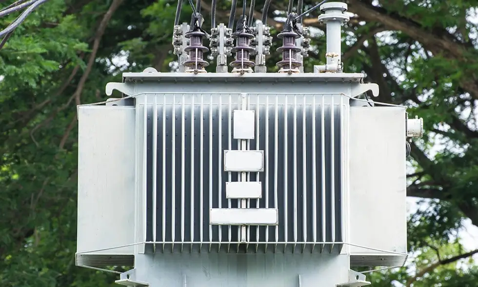
Technical parameters and dimensions
S11-M Oil-immersed transformer technical parameters
| Rated capacity (kVA) | Voltage combination | Connected group label | No-load dissipation (W) | Load dissipation (W) 75℃ | No-load current (%) | Impedance voltage (%) | Exterior size (L×W×H) Install 4-φ18 (mm) | Total Weight (kg) | ||||
| Medium voltage (kV) | Tapping range | Low voltage (kV) | L | W | H | |||||||
| 30 |
6 6.3 6.6 10 10.5 11 15 or other |
±5 ±2x2.5 |
0.38 0.4 0.415 0.44 |
Dyn11 Yyn0 Yzn11 |
100 | 630/600 | 1.5 | 4 | 690 | 510 | 920 | 275 |
| 50 | 130 | 910/870 | 1.3 | 730 | 510 | 960 | 340 | |||||
| 63 | 150 | 1090/1040 | 1.2 | 750 | 550 | 1000 | 385 | |||||
| 80 | 180 | 1310/1250 | 1.2 | 790 | 620 | 1020 | 450 | |||||
| 100 | 200 | 1580/1500 | 1.1 | 790 | 700 | 1040 | 520 | |||||
| 125 | 240 | 1890/1800 | 1.1 | 840 | 800 | 1070 | 625 | |||||
| 160 | 280 | 2310/2200 | 1 | 1070 | 670 | 1130 | 695 | |||||
| 200 | 340 | 2730/2600 | 1 | 1140 | 750 | 1140 | 795 | |||||
| 250 | 400 | 3200/3050 | 0.9 | 1200 | 800 | 1190 | 955 | |||||
| 315 | 480 | 3830/3650 | 0.9 | 1300 | 860 | 1210 | 1085 | |||||
| 400 | 570 | 4520/4300 | 0.8 | 1380 | 900 | 1240 | 1290 | |||||
| 500 | 680 | 5410/5100 | 0.8 | 1450 | 950 | 1300 | 1590 | |||||
| 630 |
Dyn11 Yyn0 |
810 | 6200 | 0.6 | 4.5 | 1500 | 970 | 1360 | 1850 | |||
| 800 | 980 | 7500 | 0.6 | 4 | 1660 | 1140 | 1400 | 2210 | ||||
| 1000 | 1150 | 10300 | 0.6 | 1690 | 1190 | 1530 | 2570 | |||||
| 1250 | 1360 | 12000 | 0.5 | 1760 | 1230 | 1600 | 3115 | |||||
| 1600 | 1640 | 14500 | 0.5 | 1800 | 1250 | 1660 | 3520 | |||||
| 2000 | 1940 | 18300 | 0.4 | 5 | 1930 | 1360 | 1490 | 4060 | ||||
| 2500 | 2290 | 21200 | 0.4 | 2080 | 1360 | 1570 | 5105 | |||||
Note 1: For transformers with rated capacity of 500kVA and below, the load loss values above the diagonal line in the table are applicable to the Dyn11 or Yzn11 coupling group, and the load loss values below the diagonal line are applicable to the Yyn0 coupling group.
Note 2: When the average annual load rate of the transformer is between 35% and 40%, the maximum operating efficiency can be obtained by using the loss value in the table.
S11-M Oil-immersed transformer dimensions
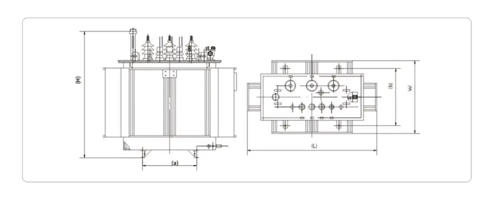
Notes: The dimensions and weights provided are only for reference in design and selection. The final size and weight are subject to our product drawings.
S13-M Oil-immersed transformer technical parameters
| Rated capacity (kVA) | Voltage combination | Connected group label | No-load dissipation (W) | Load dissipation (W) 145℃ | No-load current (%) | Impedance voltage (%) | Exterior size (L×W×H) Install 4-φ18 (mm) | Total Weight (kg) | ||||
| Medium voltage (kV) | Tapping range | Low voltage (kV) | L | W | H | |||||||
| 30 |
6 6.3 6.6 10 10.5 11 15 or other |
±5 ±2x2.5 |
0.38 0.4 0.415 0.44 |
Dyn11 Yyn0 Yzn11 |
80 | 630/600 | 1.5 | 4 | 695 | 490 | 860 | 260 |
| 50 | 100 | 910/870 | 1.3 | 725 | 520 | 955 | 365 | |||||
| 63 | 110 | 1090/1040 | 1.2 | 750 | 535 | 970 | 415 | |||||
| 80 | 130 | 1310/1250 | 1.2 | 770 | 565 | 985 | 465 | |||||
| 100 | 150 | 1580/1500 | 1.2 | 800 | 595 | 1000 | 545 | |||||
| 125 | 170 | 1890/1800 | 1.1 | 815 | 670 | 1010 | 585 | |||||
| 160 | 200 | 2310/2200 | 1.1 | 1015 | 645 | 1055 | 695 | |||||
| 200 | 240 | 2730/2600 | 1 | 1020 | 650 | 1115 | 810 | |||||
| 250 | 290 | 3200/3050 | 1 | 1140 | 730 | 1120 | 930 | |||||
| 315 | 340 | 3830/3650 | 0.9 | 1195 | 785 | 1175 | 1075 | |||||
| 400 | 410 | 4520/4300 | 0.9 | 1265 | 855 | 1195 | 1255 | |||||
| 500 | 480 | 5410/5100 | 0.8 | 1325 | 915 | 1240 | 1435 | |||||
| 630 |
Dyn11 Yyn0 |
570 | 6200 | 0.8 | 4.5 | 1465 | 960 | 1295 | 1880 | |||
| 800 | 700 | 7500 | 0.6 | 4 | 1515 | 995 | 1340 | 2145 | ||||
| 1000 | 830 | 10300 | 0.6 | 1605 | 1095 | 1460 | 2455 | |||||
| 1250 | 970 | 12000 | 0.5 | 1685 | 1145 | 1485 | 2840 | |||||
| 1600 | 1170 | 14500 | 0.5 | 1775 | 1225 | 1580 | 3310 | |||||
| 2000 | 1550 | 18300 | 0.4 | 5 | 1855 | 1265 | 1600 | 3960 | ||||
| 2500 | 1830 | 21200 | 0.4 | 1885 | 1305 | 1780 | 4980 | |||||
Note 1: For transformers with rated capacity of 500kVA and below, the load loss values above the diagonal line in the table are applicable to the Dyn11 or Yzn11 coupling group, and the load loss values below the diagonal line are applicable to the Yyn0 coupling group.
Note 2: When the average annual load rate of the transformer is between 35% and 40%, the maximum operating efficiency can be obtained by using the loss value in the table.
S13-M Oil-immersed transformer dimensions
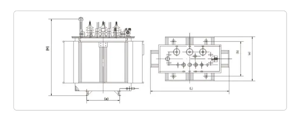
Notes: The dimensions and weights provided are only for reference in design and selection. The final size and weight are subject to our product drawings.
S14-M Oil-immersed transformer technical parameters
| Rated capacity (kVA) | Voltage combination | Connected group label | No-load dissipation (W) | Load dissipation (W) 75℃ | No-load current (%) | Impedance voltage (%) | Exterior size L×W×H (mm) | Total Weight (kg) | ||
| Medium voltage (kV) | Tapping range | Low voltage (kV) | Install 4-φ18 | |||||||
| 30 |
6 6.3 6.6 10 10.5 11 15 or other |
±5 ±2x2.5 |
0.38 0.4 0.415 0.44 |
Dyn11 Yyn0 Yzn11 |
80 | 505/480 | 1.5 | 4 | 785×710×880 | 370 |
| 50 | 100 | 730/695 | 1.3 | 800×730×940 | 480 | |||||
| 63 | 110 | 870/830 | 1.2 | 815×720×970 | 535 | |||||
| 80 | 130 | 1050/1000 | 1.2 | 830×740×990 | 580 | |||||
| 100 | 150 | 1260/1200 | 1.1 | 875×790×1010 | 705 | |||||
| 125 | 170 | 1510/1440 | 1.1 | 875×770×1050 | 775 | |||||
| 160 | 200 | 1850/1760 | 1 | 935×820×1140 | 975 | |||||
| 200 | 240 | 2180/2080 | 1 | 995×870×1140 | 1140 | |||||
| 250 | 290 | 2560/2440 | 0.9 | 995×900×1180 | 1240 | |||||
| 315 | 340 | 3060/2920 | 0.9 | 1030×880×1250 | 1425 | |||||
| 400 | 410 | 3610/3440 | 0.8 | 1075×910×1270 | 1635 | |||||
| 500 | 480 | 4330/4120 | 0.8 | 1120×930×1320 | 1950 | |||||
| 630 |
Dyn11 Yyn0 |
570 | 4960 | 0.6 | 4.5 | 1165×950×1350 | 2150 | |||
| 800 | 700 | 6000 | 0.6 | 4 | 1210×1050×1390 | 2515 | ||||
| 1000 | 830 | 8240 | 0.6 | 1520×1020×1450 | 2635 | |||||
| 1250 | 970 | 9600 | 0.5 | 1630×1090×1540 | 3210 | |||||
| 1600 | 1170 | 11600 | 0.5 | 1680×1150×1600 | 3905 | |||||
| 2000 | 1550 | 14600 | 0.4 | 5 | 1890×1300×1600 | 4130 | ||||
| 2500 | 1830 | 16900 | 0.4 | 1990×1360×1700 | 5250 | |||||
Note 1: For transformers with rated capacity of 500kVA and below, the load loss values above the diagonal line in the table are applicable to the Dyn11 or Yzn11 coupling group, and the load loss values below the diagonal line are applicable to the Yyn0 coupling group.
Note 2: When the average annual load rate of the transformer is between 35% and 40%, the maximum operating efficiency can be obtained by using the loss value in the table.
S14-M Oil-immersed transformer dimensions
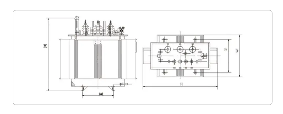
Notes: The dimensions and weights provided are only for reference in design and selection. The final size and weight are subject to our product drawings.
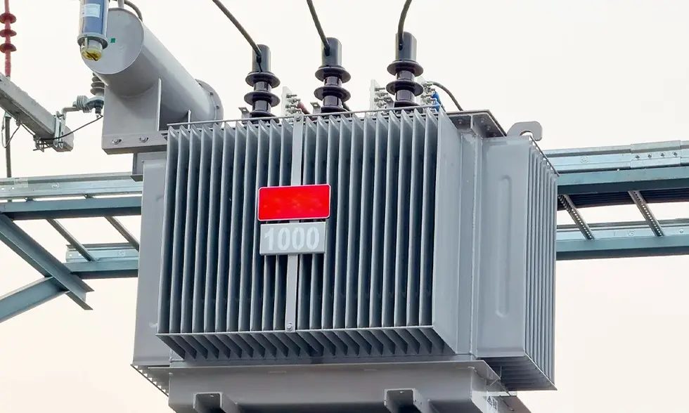
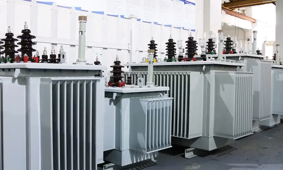
Products Show
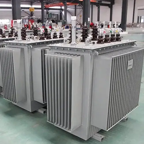
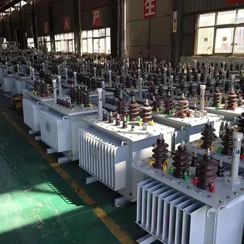
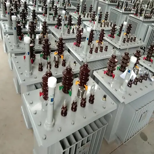
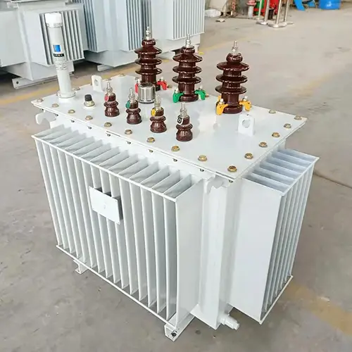
Hot Tags: 10kV Oil Immersed Distribution Power Transformer, China, Manufacturer, Supplier, Factory
Related Category
Send Inquiry
Contact Info
-
Address
Building 2, Changhong Industrial Park, No. 501 Liule Road, Liushi Town, Yueqing City, Wenzhou City, Zhejiang Province, China
-
Tel
-
E-mail
Mobile/WhatsApp: