Products
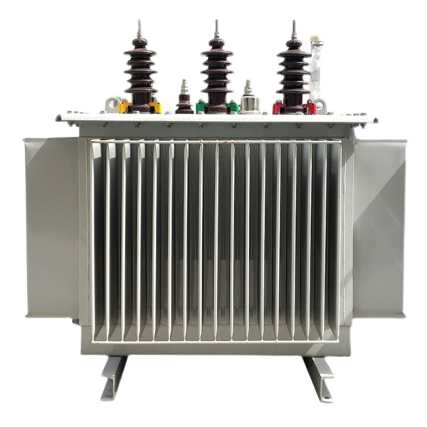
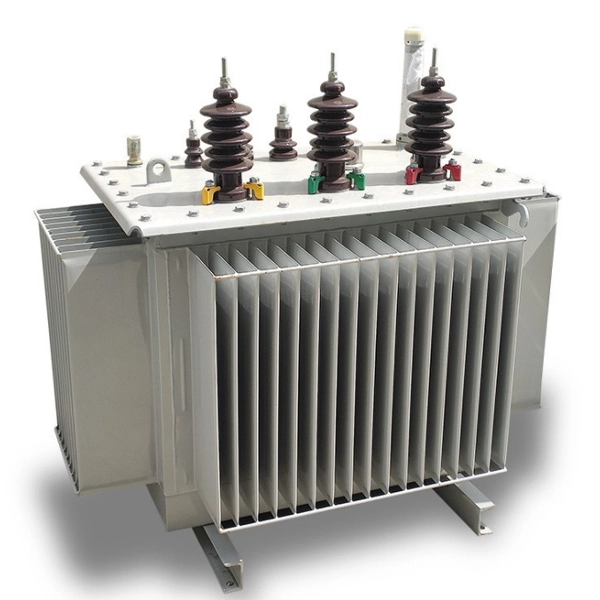
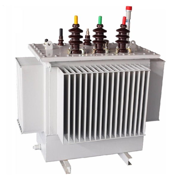
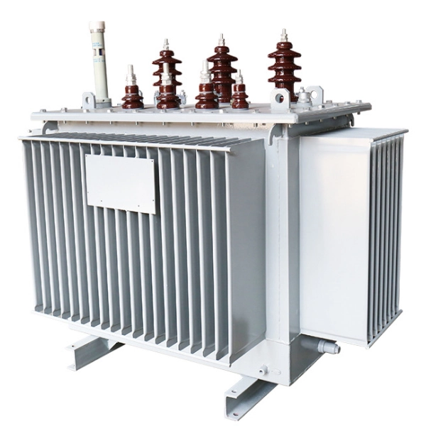
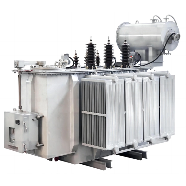
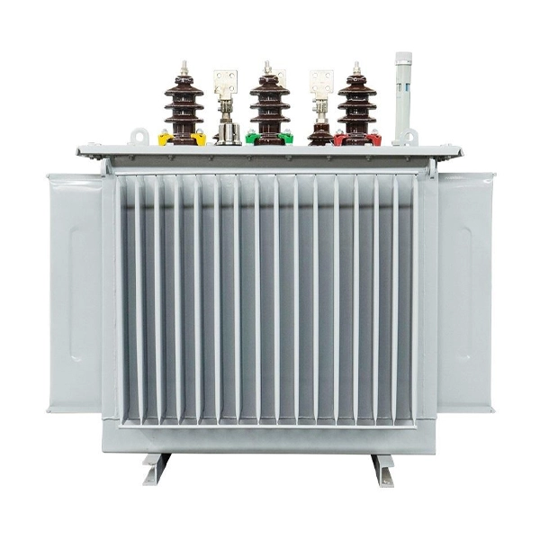
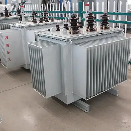
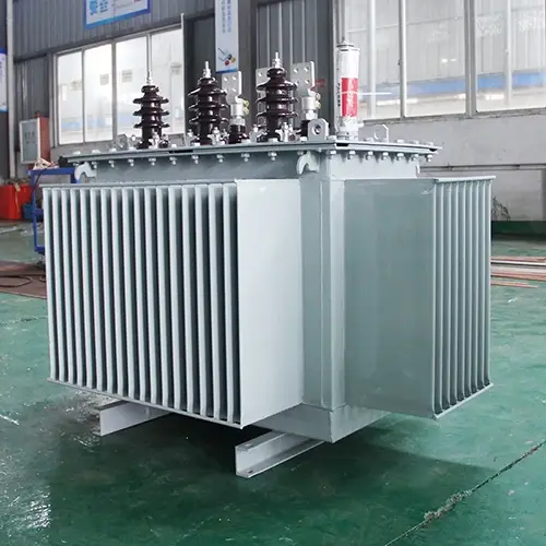
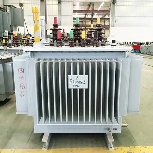
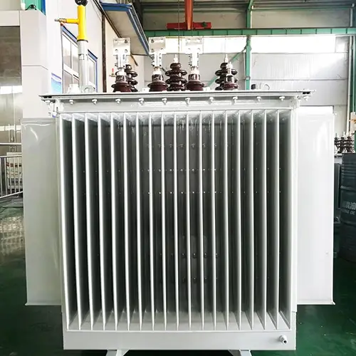
20KV Oil Immersed Type Electrical Transformer
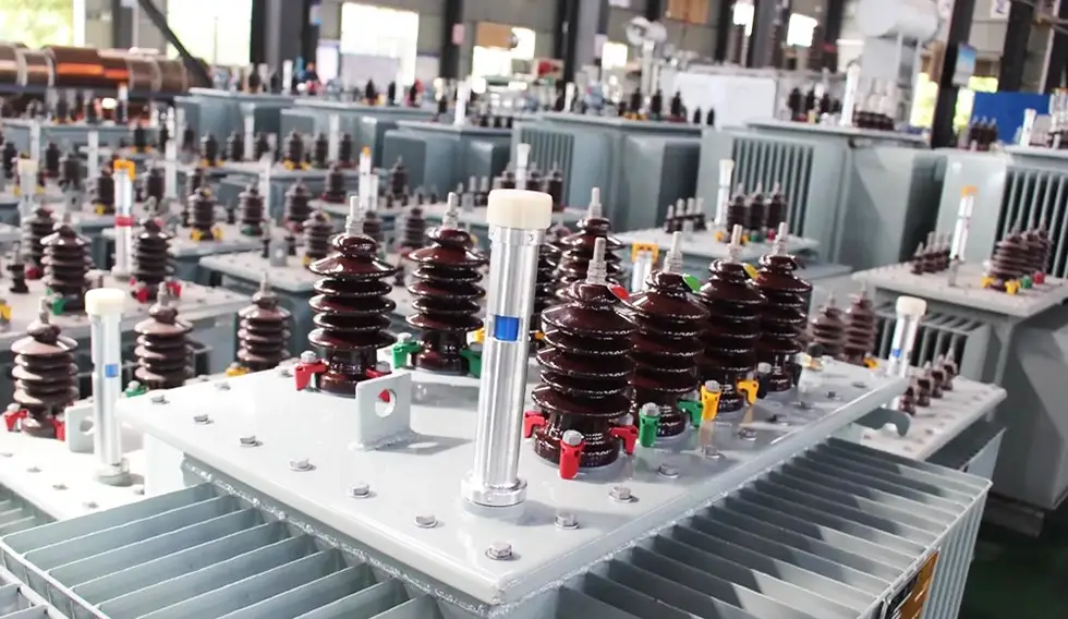
Cotenele is a large electrical transformer manufacturer and exporter from China. Over the years, we have provided a large number of high-quality electrical transformer products to domestic and overseas customers. The 20KV Oil Immersed Type Electrical Transformer we produced have reliable quality and stable performance, and have received widespread praise from customers over the years. All of the power transformers we produced comply with relevant standards such as IEC60076, GB/T 6451-2023, GB 1094, etc
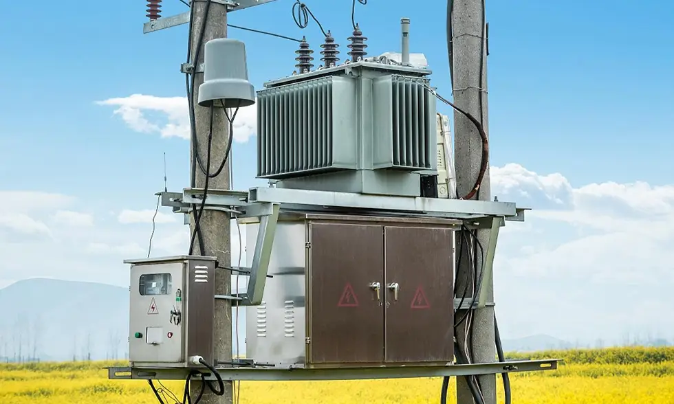
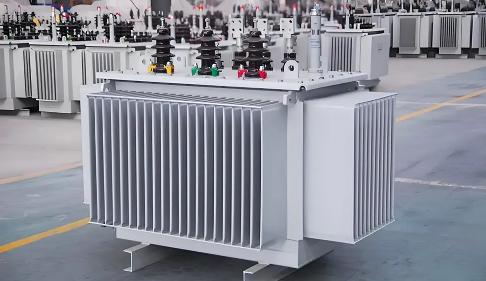
The electrical transformer is one of products which is produced by Cotenele. Our 20KV Oil Immersed Type Electrical Transformer is a power distribution device that steps down the 20kV voltage level to low voltage (typically 0.4kV). It is widely used in 20kV distribution systems. As power grids are upgraded, the 20kV system offers significant advantages over the 10kV system: for the same transmitted power, the line current is reduced by 50%, and line energy losses are decreased by 75%, resulting in remarkable energy savings and capacity expansion. The 20KV Oil Immersed Type Electrical Transformers are mainly used in power distribution networks, industrial and mining enterprises, commercial and civil buildings, and other scenarios.
Main technical parameters
| Rated capacity (kVA) | Voltage ratio (kV) | Connection Symbol | Loss (W) | No-load current (%) | Impedance (%) | Weight (kg) | Outline Dimension (mm) | Gauge (mm) | |||||
| Medium voltage | Low voltage | No-load Loss | Full-load Loss | Oil weight | Total weight | L | W | H | |||||
| 30 |
20 ±5% Or ±2×2.5% |
0.4 |
Yyn0 Dyn11 |
100 | 690/660 | 2.1 | 5.5 | 100 | 360 | 800 | 680 | 950 | 400×400 |
| 50 | 130 | 1010/960 | 2 | 120 | 410 | 850 | 700 | 970 | 400×400 | ||||
| 63 | 150 | 1200/1150 | 1.9 | 140 | 480 | 880 | 710 | 1000 | 400×400 | ||||
| 80 | 180 | 1440/1370 | 1.8 | 150 | 540 | 900 | 720 | 1030 | 400×400 | ||||
| 100 | 200 | 1730/1650 | 1.6 | 170 | 615 | 950 | 750 | 1050 | 400×400 | ||||
| 125 | 240 | 2080/1980 | 1.5 | 180 | 710 | 950 | 900 | 1070 | 550×550 | ||||
| 160 | 290 | 2540/2420 | 1.4 | 195 | 790 | 1000 | 900 | 1100 | 550×550 | ||||
| 200 | 340 | 3000/2860 | 1.3 | 220 | 910 | 1050 | 930 | 1120 | 550×550 | ||||
| 250 | 400 | 3520/3350 | 1.2 | 245 | 1040 | 1100 | 950 | 1150 | 550×550 | ||||
| 315 | 480 | 4210/4010 | 1.1 | 280 | 1185 | 1450 | 950 | 1200 | 550×550 | ||||
| 400 | 570 | 4970/4730 | 1 | 300 | 1370 | 1500 | 1000 | 1250 | 660×660 | ||||
| 500 | 680 | 5940/5660 | 1 | 350 | 1620 | 1550 | 1050 | 1320 | 660×660 | ||||
| 630 | 810 | 6820 | 0.9 | 420 | 2085 | 1650 | 1100 | 1350 | 660×660 | ||||
| 800 | 980 | 8250 | 0.8 | 6 | 465 | 2400 | 1700 | 1200 | 1450 | 820×820 | |||
| 1000 | 1150 | 11330 | 0.7 | 580 | 2880 | 1900 | 1350 | 1500 | 820×820 | ||||
| 1250 | 1380 | 13200 | 0.7 | 640 | 3300 | 1950 | 1380 | 1550 | 820×820 | ||||
| 1600 | 1660 | 15950 | 0.6 | 770 | 4000 | 2050 | 1450 | 1600 | 820×820 | ||||
Product Classification
The 20kV oil-immersed distribution transformers can be classified according to the following criteria:
1. By number of phases
Single-phase transformers: capacity range 5kVA -160kVA
Three-phase transformers: capacity range 30kVA -2500kVA
2. By core material
Silicon-steel transformers: models include S11, S13, S20, S22 series
Amorphous-alloy transformers: models include SBH15, SBH21, SBH25 series; their no-load losses are approximately half those of silicon-steel transformers of the same energy-efficiency class
3. By energy-efficiency rating
Mid-to-high-end products: S13, S20, S22, and amorphous-alloy series
Low-end products: S11 series
4. By tap-changing method
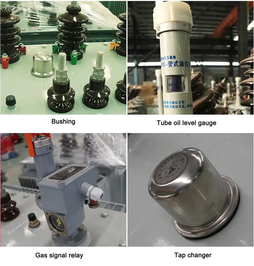
Off-circuit (no-load) tap-changing: requires de-energisation for manual adjustment
On-load tap-changing: allows adjustment while energised (available on some models)
5. By tank enclosure type
Fully sealed type, conventional type, etc.
Application Scope of the 20kV oil-immersed distribution transformers
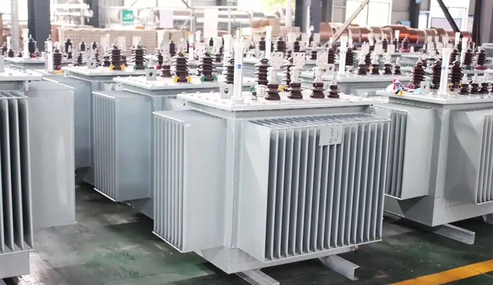
20kV oil-immersed distribution transformers are mainly used in the following scenarios:
1. Power distribution networks: urban and rural distribution grids, 20kV distribution lines
2. Industrial and mining enterprises: petroleum, metallurgy, chemical, textile, light industry, etc.
3. Commercial and residential buildings: commercial complexes, office buildings, residential quarters
4. Special environments: locations with high dust, oil contamination, or chemical substances
5. Dual-voltage switching applications: some models can operate on either 10kV or 20kV systems by switching between voltage levels
Working Principle
The working principle of a 20kV oil-immersed distribution transformer is electromagnetic induction:
1. When the AC power voltage is applied to the primary winding (high voltage side, 20kV), the AC current passes through the winding and generates alternating magnetic flux in the iron core.
2. This alternating flux simultaneously links both the primary and secondary windings (low-voltage side, typically 0.4kV).
3. According to the law of electromagnetic induction, electromotive forces are induced in both windings.
4. Since the two windings have different numbers of turns, the induced voltages differ accordingly -- the turns ratio equals the voltage ratio.
5. The heat generated during operation is transferred through the insulating oil to the tank wall, and then dissipated to the surrounding air via cooling fins (or corrugated panels).
How to choose the suitable power electrical transformer
1. Capacity selection
- Calculate the total connected load from all electrical equipment and facilities (generally excluding fire-fighting loads).
- The compensated apparent power serves as the basis for selecting transformer capacity and number of units.
- Generally, the transformer load factor should be kept at about 85%.
- Avoid oversized transformers or overloading.
2. Model selection
- S11 series: low-end products, suitable for applications with low energy-efficiency requirements.
- S13/S20/S22 series: mid-to-high-end energy-saving products.
- Amorphous-alloy series (SBH15, etc.): extremely low no-load losses, ideal for applications with long idle times and high emphasis on energy saving.
3. Other considerations
- Installation environment (indoor / outdoor)
- Fire-protection rating requirements
- Need for dual-voltage switching (10kV/20kV compatibility)
- Tap-changing method (off-circuit or on-load)
- Budget and cost constraints
Products details
Products Appearance and dimensions
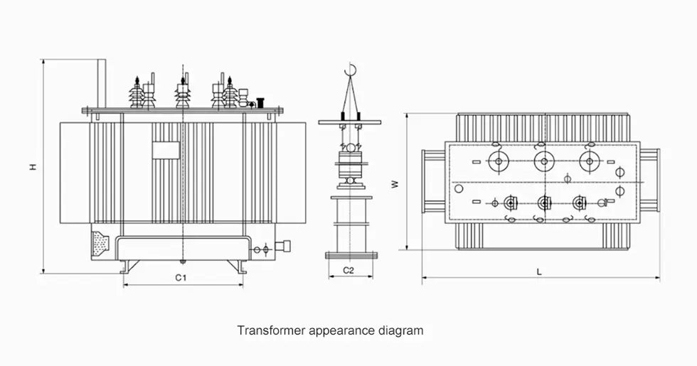
| Product Appearance and installation dimensions | |||||
| Rated capacity (kVA) | L | W | H | C1 | C2 |
| 30 | 950 | 650 | 880 | 400 | 400 |
| 50 | 1000 | 650 | 900 | 400 | 400 |
| 63 | 1020 | 720 | 960 | 400 | 400 |
| 80 | 1080 | 730 | 990 | 400 | 400 |
| 100 | 1090 | 760 | 1050 | 400 | 500 |
| 125 | 1120 | 780 | 1080 | 550 | 550 |
| 160 | 1160 | 810 | 1130 | 550 | 550 |
| 200 | 1210 | 850 | 1180 | 550 | 550 |
| 250 | 1220 | 860 | 1220 | 550 | 550 |
| 315 | 1380 | 900 | 1260 | 550 | 550 |
| 400 | 1430 | 920 | 1290 | 550 | 660 |
| 500 | 1530 | 960 | 1360 | 550 | 660 |
| 630 | 1680 | 1000 | 1400 | 660 | 660 |
| 800 | 1700 | 1100 | 1480 | 660 | 820 |
| 1000 | 1750 | 1150 | 1520 | 660 | 820 |
| 1250 | 1850 | 1210 | 1600 | 660 | 820 |
| 1600 | 2000 | 1280 | 1690 | 820 | 820 |
| 2000 | 2280 | 1360 | 1850 | 820 | 820 |
| 2500 | 2580 | 1890 | 2100 | 820 | 820 |
Ordering Notice
When placing an order, the product model, rated capacity, high and low voltage rated voltage, high voltage tap range, number of phases, frequency, and connection group number should be provided.
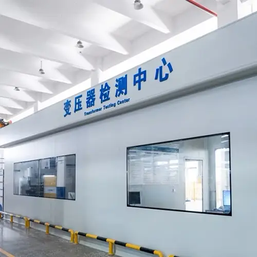
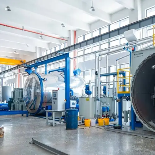
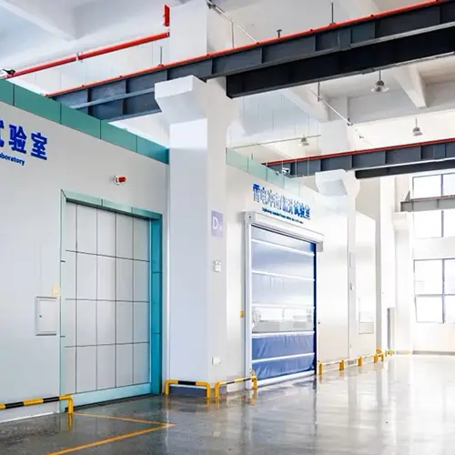
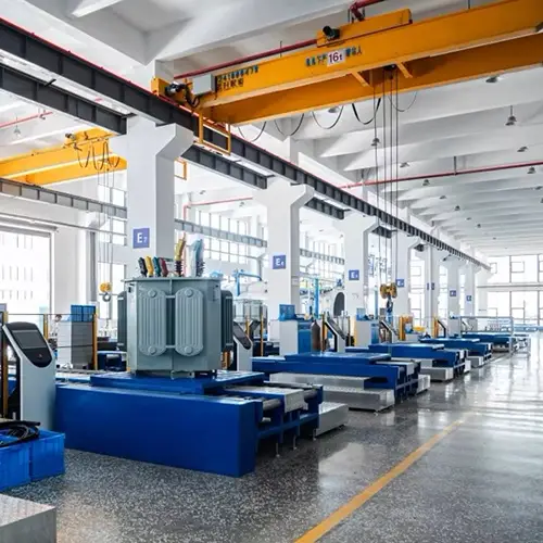
Workshop and Testing Center
Products Show
Hot Tags:
Related Category
Send Inquiry
Contact Info
-
Address
Building 2, Changhong Industrial Park, No. 501 Liule Road, Liushi Town, Yueqing City, Wenzhou City, Zhejiang Province, China
-
Tel
-
E-mail
Mobile/WhatsApp: